
Computer system

Inactive Publication Date: 2008-08-21
HITACHI LTD
View PDF5 Cites 11 Cited by
  • Summary
  • Abstract
  • Description
  • Claims
  • Application Information

AI Technical Summary

Benefits of technology

[0012]It is therefore an object of the present invention to provide a technique for suppressing the need of active device check by an administrator by providing log data to the administrator for judging whether hardware is to be replaced.
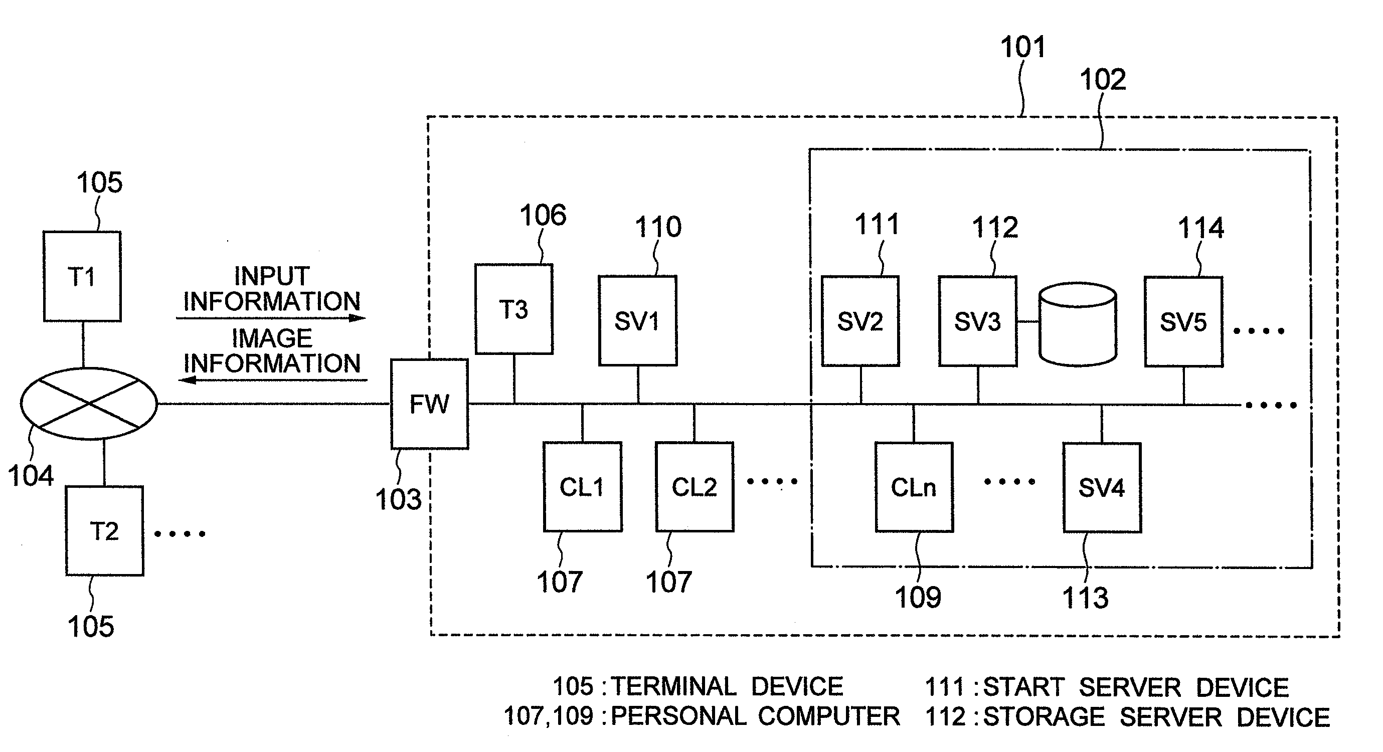
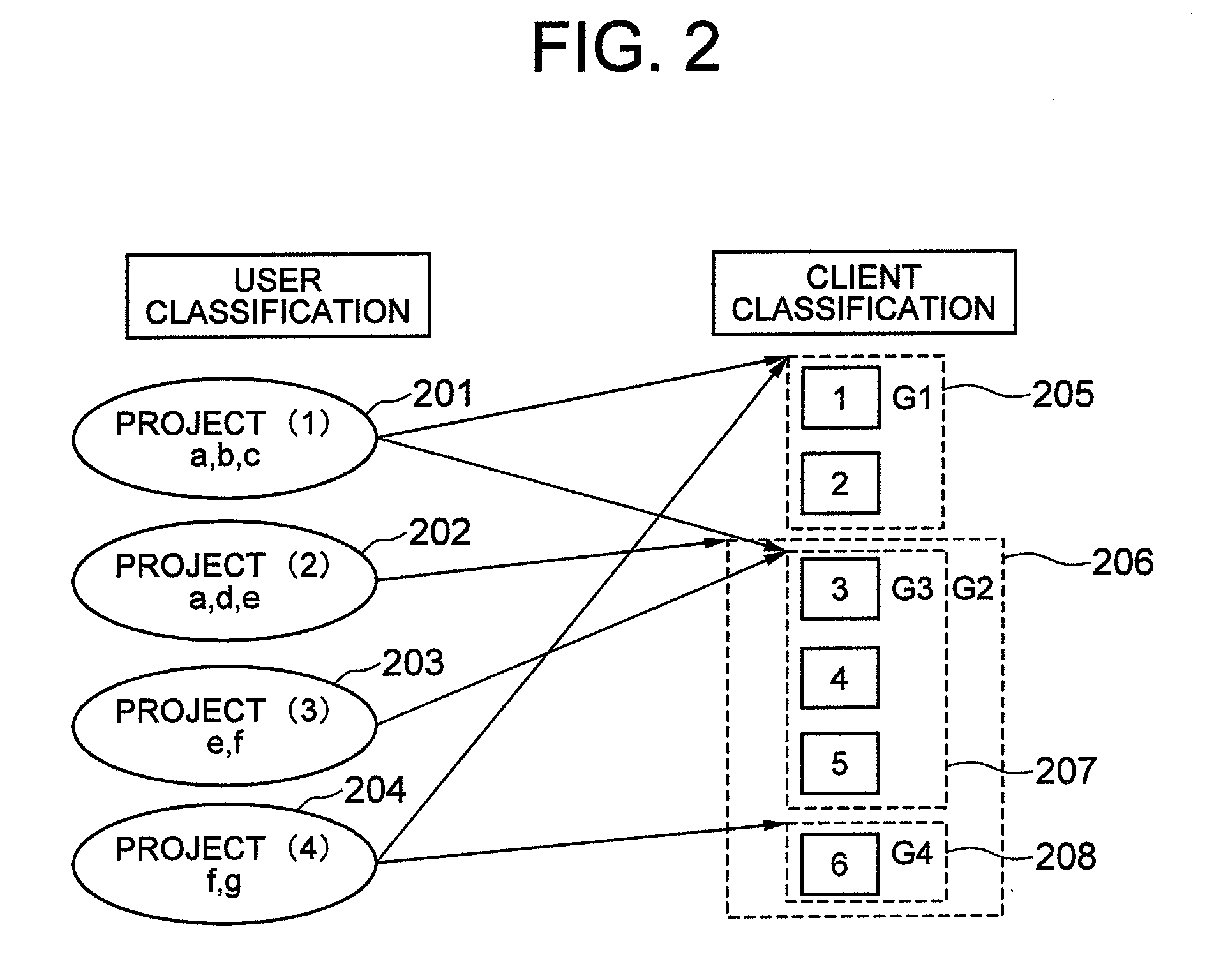
[0018]Firstly, a user is not fixed to each of the personal computers. The user, as a member of a group or an organization to which the user belongs, makes a connection request from a terminal device to a personal computer group appropriate for the performance, the function, and the application appropriate for performing a job of the group or the organization and uses it. From the viewpoint of the administrator side, it is requested to perform such an operation that a plurality of groups or organizations are connected to a plurality of computer groups and a higher-priority use is permitted according to an individual attribute and a time elapse. Here, computer groups to be used with a higher priority by a group to which individuals belong or a member of the group are managed as a table, so that when a use request of a personal computer is received from the terminal device, the start server device automatically searches for an appropriate personal computer by itself. The administrator can perform policy registration of preset how to make the system behave when the start server device has failed in allocation or resources are actually insufficient, so as to semi-automate the operation and reduce TCO.
[0020]This invention can reduce the recovery work by a user who is forced to interrupt a job in spite of that no hardware has failed and an administrator. That is, when a personal computer system has failed and the system cannot be started because of a hardware failure or the system is unstable even if it can be started, log data used for judging whether to replace hardware is provided to the administrator. This can suppress the need of active device check by the administrator.

Problems solved by technology

However, the aforementioned computer system techniques have some problems.

Method used


Image

  • Computer system
  • Computer system
  • Computer system

Examples


an embodiment

Outline of an Embodiment

[0027]The embodiment of the present invention may be applied to a system including a client system using a combination of a personal computer body in which an operating system and an application operate and a terminal device which remotely operates the personal computer. Moreover, the present invention may be applied to a control system which stores data inherent to a user in a place other than the personal computer or the terminal device so that when a request is made to start the personal computer via the terminal device, a data region inherent to the user is displayed as a virtual drive device or a symbolic link on the personal computer so as to be used by a user.

[0028]More specifically, the present invention is applied to a computer system including: a terminal device in which direct operation or content check is performed by a user; a plurality of personal computers which are connected to the terminal device via a network and remotely operated by the use...


PUM


Abstract

A technique for suppressing the need of active device check by an administrator by providing log data to the administrator for judging whether to replace hardware. A computer system includes: a terminal device in which a user performs direct operation or content check, a plurality of personal computers connected to the terminal device via a network and serving as objects of remote operation by the user, and a storage server device which accumulates information created or referenced by the user, and a start server device having a computer operation managing function which selects a usable personal computer and connects it to the terminal device so as to provide a use environment to the user when the user has made an allocation request to any one of the personal computers via the terminal device.

Description

BACKGROUND OF THE INVENTION[0001]The present invention relates to a technique of a computer system and in particular, to a technique which can be effectively applied to operation, maintenance, and use of a computer.[0002]The inventor of the present invention has studied about computer system techniques and has found that the following techniques are suggested from the viewpoint of security to prevent loss and leak of electronic information especially from a mobile PC.[0003](1) A computer operation technique using a so-called “dual client”. That is, instead of connecting a client terminal device directly to a shared server containing an electronic file required for performing a job, the client terminal device is connected to a personal computer for performing the job if a user authentication is successful, and an access is made from the personal computer to a job server and user's data.[0004](2) A technique for operating a particular computer via a network from a start managing serve...

Claims


Application Information

Patent Timeline
IPC IPC(8): G06F15/173
CPCH04L29/06H04L67/125H04L67/08H04L9/40
Inventor YAMADA, YASUNORI
Owner HITACHI LTD
Learn More