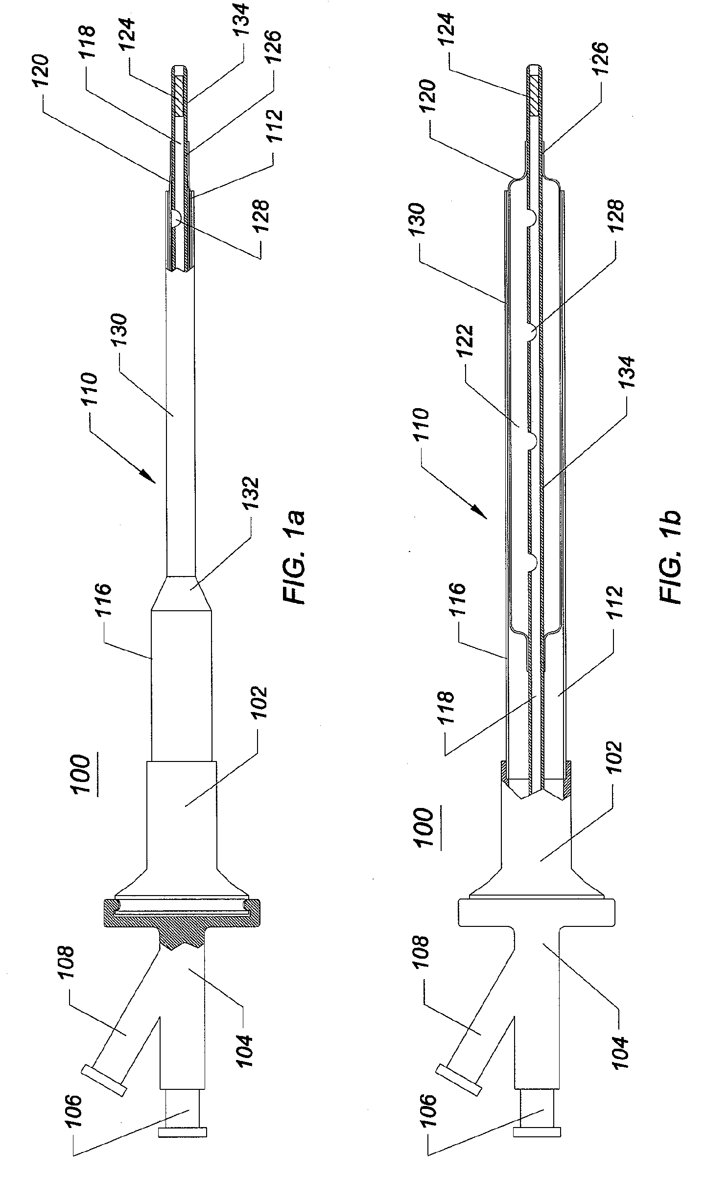
[0013]One embodiment of the invention comprises a medical access
system for providing minimally invasive access. The
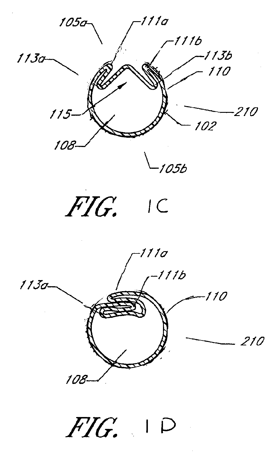
system includes an access sheath comprising an elongate tubular body that defines a lumen, at least a portion of the elongate tubular body being expandable from a first, folded, smaller cross-sectional profile to a second, greater cross-sectional profile. The expandable region of the sheath is capable of maintaining, without external constraint, its collapsed configuration when folded into a first, smaller cross-sectional
diameter.
[0017]In another embodiment of the invention, a medical access
assembly includes an elongate tubular body that defines a lumen. At least a portion of the elongate tubular structure is expandable from a first, folded, smaller cross-sectional profile to a second, greater cross-sectional profile. An expandable member is positioned within the elongate tubular body and configured to expand the elongate tubular body from the first, smaller cross-sectional profile to the second, greater cross-sectional profile. A tapered fairing is affixed to the expandable member
proximate its distal tip. The tapered fairing can be elastomeric and expand radially with the expandable member. Following collapse of the expandable member, the tapered fairing, being elastomeric collapses with the expandable member to a
diameter smaller than that of the expanded elongate tubular structure. In a further embodiment, the tapered fairing is forced forward toward the distal end of the expandable member, said forward movement facilitating disengagement between the tapered fairing and the distal end of the expandable region of the sheath.
[0019]In another embodiment, a medical access sheath
system comprises an axially elongate tubular structure having a proximal end and a distal end. At least a portion of the distal region of the axially elongate tubular structure is expandable and compressible and comprises a composite wall with malleable elements embedded therein. The malleable composite wall can be fabricated using a
polymer exterior and interior layer with a central reinforcing layer of malleable material such as annealed stainless steel sandwiched therebetween. The malleable expandable region eliminates the need for a jacket to constrain or maintain the expandable region in its compressed configuration and provides additional strength in the dilated or expanded configuration. The malleable structure exerts a force greater than the elastomeric forces applied by the polymeric structure but is unable to
resist expansion forces generated by a
dilator such as a
high pressure balloon or the like.
[0020]In another embodiment of the invention, a method of providing medical access comprises inserting a guidewire into a patient, percutaneously inserting an elongate tubular body having a first, smaller cross-sectional profile over a guidewire such that tissue is diverted from impinging on the distal edge of the elongate tubular body; expanding the elongate tubular body from the first, smaller cross-sectional profile to a second, greater cross-sectional profile; removing the expandable member from the elongate tubular body; performing diagnostic or therapeutic intervention through the elongate tubular body; and removing the elongate tubular body from the patient. In yet another embodiment, the elongate tubular body is inserted into the patient without the use of a guidewire. In this embodiment, the guidewire can be eliminated or it can be replaced with a trocar or core device, such as a hollow needle or a Veirass needle, which can be permanent or removable.
[0021]In another embodiment of the invention, a medical access sheath system comprises an elongate tubular body that defines a lumen. At least a portion of the elongate tubular structure is expandable from a first, folded, smaller cross-sectional profile to a second, greater cross-sectional profile. In an embodiment, a tapered tip is provided to aid in the
insertion of the sheath by forming a smooth transition from the dilator tip to the sheath distal end. The tapered tip is configured to protect the sheath distal end from the ingress of tissue during
insertion, said tissue ingress potentially causing the sheath to hang-up or prematurely dilate. The tapered tip is configured to protect the dilator,
balloon, or expandable member from sharp or boney tissue and hardened calculi during
insertion and positioning. In an embodiment, the transition forms a gradual taper increasing in
diameter from the distal most aspect to a more proximal aspect. Such a
gradual transition within the tapered tip increases the tactile
signal, or force feedback, from the sheath tip to the surgeon during
manual insertion and positioning. In an embodiment, the tapered tip can be coated with a hydrophilic lubricious
coating to minimize friction between the tip and surrounding tissue during introduction into the patient.
[0022]In one embodiment, where the medical access sheath is used to provide access to the
upper urinary tract, the medical access sheath may be used to provide access by tools adapted to perform
biopsy, urinary diversion,
stone extraction, antegrade endopyelotomy, and resection of transitional
cell carcinoma and other diagnostic or therapeutic procedures of the
upper urinary tract or bladder. An expandable device that does not include a restraining jacket permits a substantially increased force to be supplied to dilate the expandable region of the sheath against the radially inwardly directed tissue forces. The embodiments disclosed herein, which represent unrestrained expandable sheaths, permit increased expansion forces of 33% or more relative to sheaths that are constrained or restrained by a jacket, given the same amount of inflation force or pressure. The expandable sheaths disclosed herein comprise wall structures that are plastically deformable or malleably deformable. These sheath structures do not comprise walls that are elastomeric or resilient and thus will hold their shape once set in a certain configuration.


