
Mapping Movement of a Movable Transducer

a technology of movable transducers and mapping movements, which is applied in the field of calibration, can solve the problems of inability to calibrate an invasive probe effectively, inability to accurately measure the movement of the movable transducer, and non-uniform motion and non-linear relationship between the drive and the actual transducer motion,

Inactive Publication Date: 2008-08-21
GENERAL ELECTRIC CO
View PDF21 Cites 41 Cited by
  • Summary
  • Abstract
  • Description
  • Claims
  • Application Information

AI Technical Summary

Problems solved by technology

The mechanical rotation system (motor, driveshaft, bearings, ultrasound cables, etc.) may not be “stiff” and may have significant dynamics, causing non-uniform motion and a non-linear relationship between the drive and the actual transducer motion.
This, in turn, causes distortion of, and possibly instability in, the ultrasound image, which can make the clinical procedure more difficult, more time-consuming, less safe, or simply impossible.
To date, no suitable device or method of calibrating an invasive probe to effectively reduce distortion, such as NURD, caused during use of movable transducers is available.

Method used


Image

  • Mapping Movement of a Movable Transducer
  • Mapping Movement of a Movable Transducer
  • Mapping Movement of a Movable Transducer

Examples


Embodiment Construction

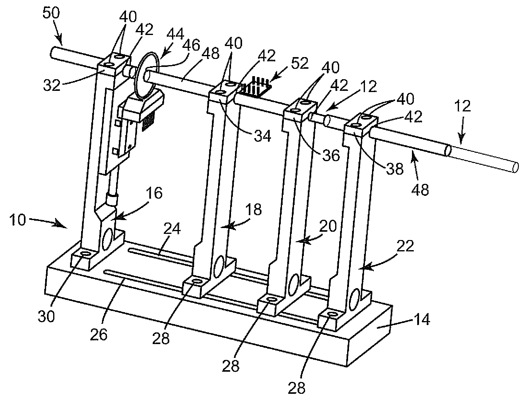
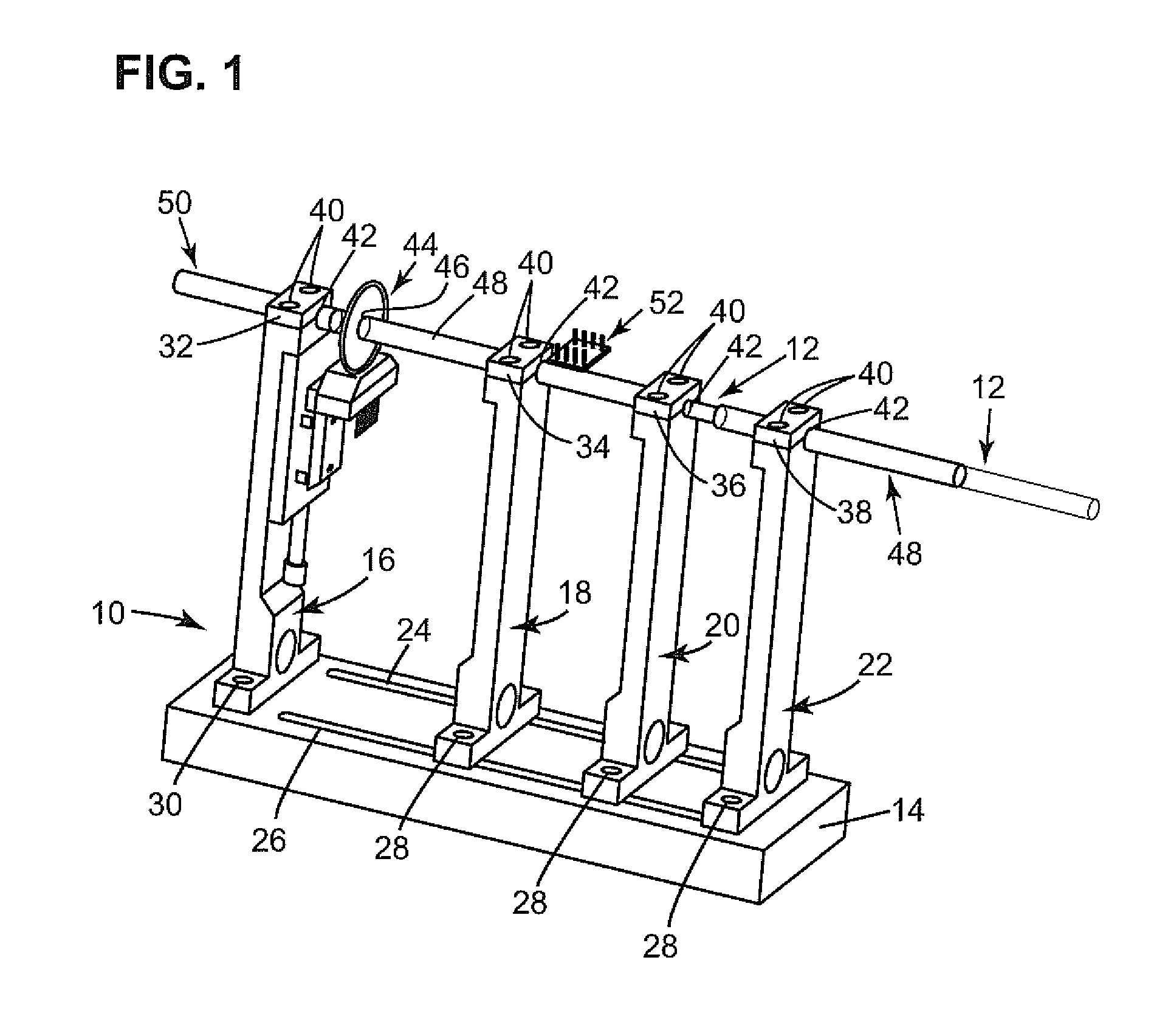
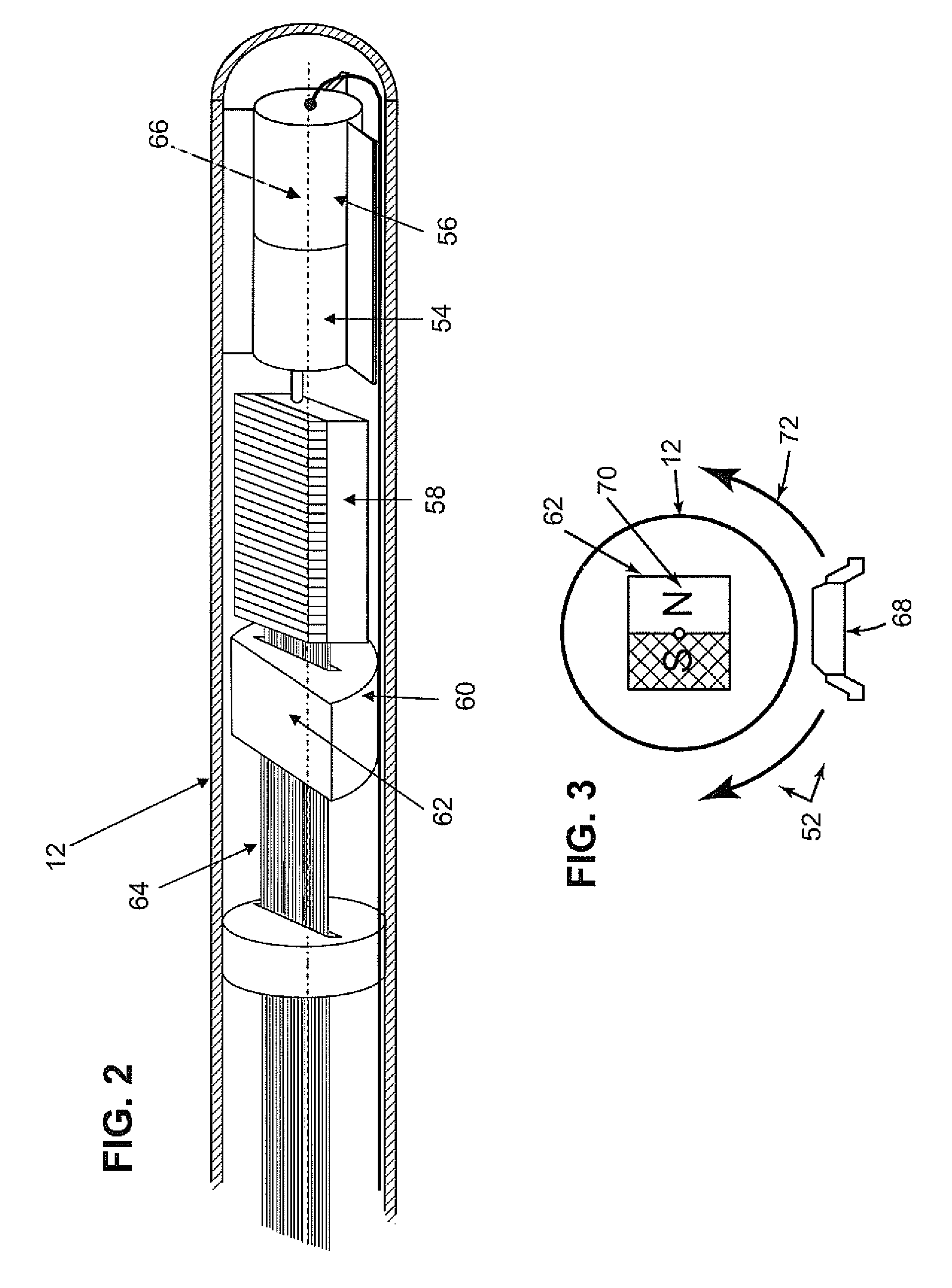
[0019]One embodiment of the present invention concerns a device and a method for mapping movement of a transducer within a probe usable to reduce distortions and instability in an ultrasound image and to make the clinical procedure easier, less time-consuming and safer. In the present embodiment, the actual position, e.g. the rotation angle, of a transducer that undergoes at least one cycle of angular movement, is sensed and this information may be used to reduce the distortion, such as non-uniform rotational distortion (NURD). In one particular embodiment, an ultrasound probe is supported by test fixture and a sensor is provided for identifying a position of the transducer throughout the angular cycle of movement.

[0020]Referring now to FIG. 1, a test fixture and a probe, in accordance with one embodiment of the present invention, are illustrated generally at 10 and 12, respectively. In this embodiment, the test fixture 10 comprises a base 14 and a plurality of probe support members...


PUM


Abstract

A catheter probe includes a transducer configured for at least one cycle of movement within the probe and a sensor that is at least partially supported within the probe for identifying a position of the transducer during the at least one cycle of movement. A method of mapping movement and a test fixture are also presented.

Description

BACKGROUND OF THE INVENTION[0001]1. Field of the Invention[0002]The subject matter described herein relates generally to calibration and, more particularly, to calibrating movable transducers to avoid distortion.[0003]2. Related Art[0004]Current medical diagnostic demands require reducing an outer diameter of an invasive body such as a catheter to allow the catheter to travel through the narrow and tortuous regions of a patient's vascular system. Contained within the tubular body may be a mechanical rotation system that includes e.g., a motor, a driveshaft, and bearings. The motor may be used to rotate a transducer to acquire a real-time two-dimensional or three-dimensional image. The mechanical rotation system (motor, driveshaft, bearings, ultrasound cables, etc.) may not be “stiff” and may have significant dynamics, causing non-uniform motion and a non-linear relationship between the drive and the actual transducer motion. This, in turn, causes distortion of, and possibly instabil...

Claims


Application Information

Patent Timeline
Patent Type & Authority Applications(United States)
IPC IPC(8): A61B5/00G01D11/00G01D11/30
CPCA61B8/12A61B8/58A61B8/445G01D11/30A61B2017/00725
Inventor WILDES, DOUGLAS GLENNWELLES, KENNETH BRAKELEYPLOTNIKOV, YURY ALEXEYEVICHGRIFFIN, WESTON BLAINEMAY, ANDRZEJ
Owner GENERAL ELECTRIC CO
Learn More