
Oscillator

Inactive Publication Date: 2008-08-21
SONY CORP
View PDF6 Cites 7 Cited by
  • Summary
  • Abstract
  • Description
  • Claims
  • Application Information

AI Technical Summary

Benefits of technology

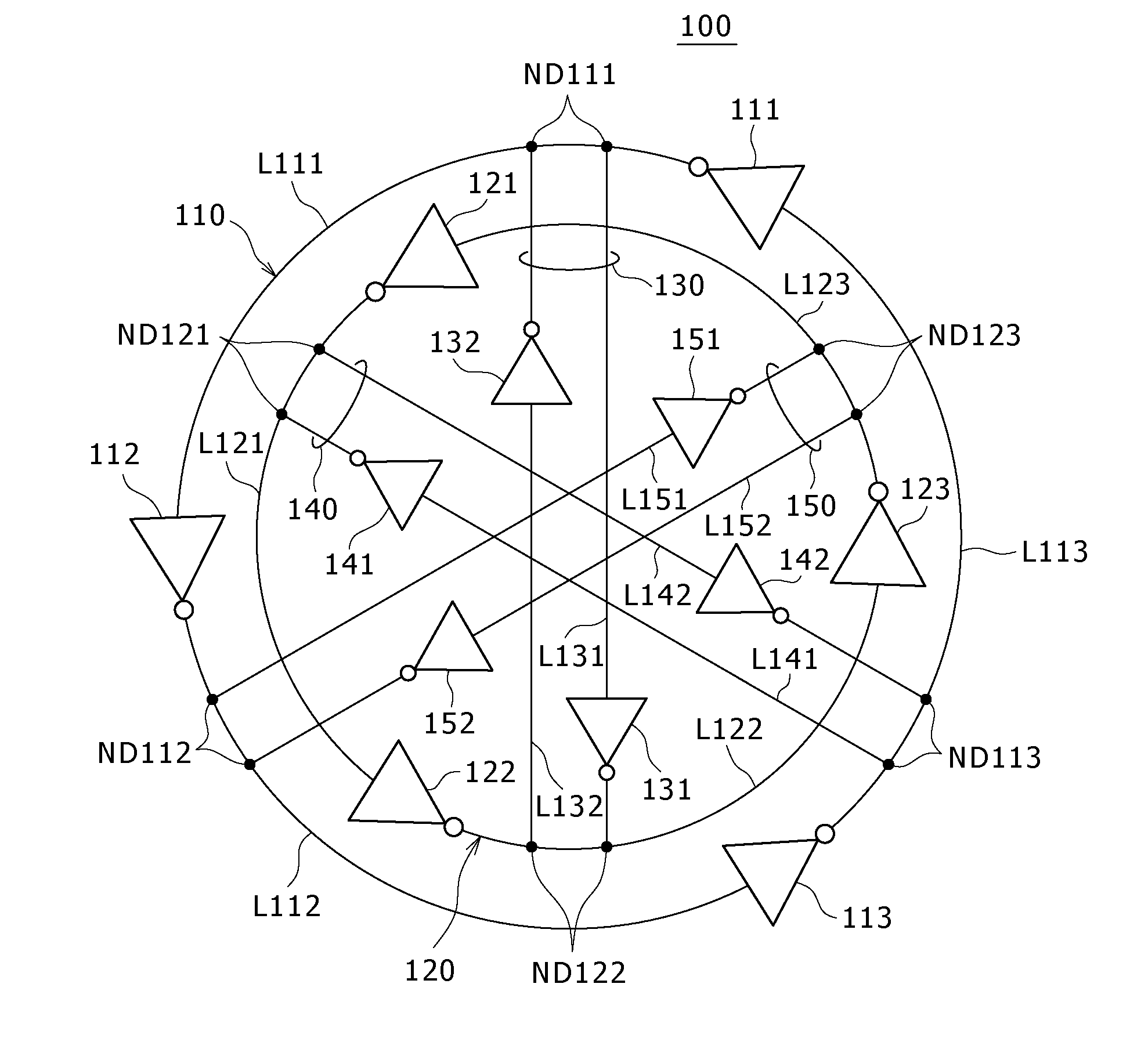
[0033]The present invention provides an oscillation circuit capable of generating distributed oscillation signals that have a low sensitivity to variations in power-supply voltage, an oscillation frequency variable over a wide range, a good jitter performance, a good phase-noise performance and a plurality of phases shifted from each other by a fixed difference.
[0044]In accordance with the present invention, it is possible to implement a high-speed ring oscillation circuit capable of generating distributed differential signals that have a low sensitivity to variations in power-supply voltage, an oscillation frequency variable over a wide range, a good jitter performance, a good phase-noise performance and a plurality of phases shifted from each other by a fixed difference and implement a PLL circuit employing the high-speed ring oscillation circuit.

Problems solved by technology

Since this technology is the technology of the single-end type ring VCO, the proposed ring VCO raises a problem that the sensitivity to variations in power-supply voltage is as high as the single-end type ring VCO in the past.
In addition, the proposed ring VCO also raises another problem that the proposed ring VCO does not have a symmetrical structure constructed between the power-supply line and the ground line so that the proposed ring VCO does not have a good jitter performance and a good phase-noise performance.

Method used


Image

  • Oscillator
  • Oscillator
  • Oscillator

Examples


first embodiment

[0103]FIG. 9 is a diagram showing a first embodiment implementing the oscillation circuit 100 shown in FIG. 5.

[0104]FIGS. 10A, 10B and 10C are diagrams showing elements obtained by decomposing the first embodiment shown in FIG. 9. To be more specific, FIGS. 10A and 10B show the first and second three-stage inverter rings 110 and 120 respectively whereas FIG. 10C shows a coupling latch (or the inverter pairs 130, 140 and 150).

[0105]In this embodiment, the first three-stage inverter ring 110 is seen as an equilateral triangle having the connection paths L111, L112 and L113 as its sides and the nodes ND111, ND112 and ND113 as its vertexes as shown in FIG. 10A. By the same token, the second three-stage inverter ring 120 is seen as an equilateral triangle having the connection paths L121, L122 and L123 as its sides and the nodes ND121, ND122 and ND123 as its vertexes as shown in FIG. 10B. If the nodes ND111, ND112, ND113, ND121, ND122 and ND123 are placed on the circumference of a circle...

second embodiment

[0117]FIGS. 11A and 11B are each a diagram showing the configuration of an oscillation core including two three-stage inverter rings in accordance with the The configurations shown in the figures are different from each other in that, in the case of the configuration shown in FIG. 11A, the direction of the additional inverters is the counterclockwise direction, which is the same direction as that of the inverters employed in the first and second three-stage inverter rings but, in the case of the configuration shown in FIG. 11B, the direction of the additional inverters is the clockwise direction, which is a direction opposite to that of the inverters employed in the first and second three-stage inverter rings.

[0118]To put it concretely, in the case of the typical configuration shown in FIG. 11A, an additional inverter 171 connects the node ND111 of the first three-stage inverter ring 110 to the node ND121 of the second three-stage inverter ring 120, being oriented in the direction ...


PUM


Abstract

The present invention provides an oscillation circuit including: a plurality of multi-stage inverter rings each having an odd number of inverters connected to each other in cascade to form a ring through the same odd number of nodes on the ring; an inverter group for connecting each one of the nodes on any specific one of the multi-stage inverter rings to a counterpart one of the nodes on another one of the multi-stage inverter rings so as to join the specific and other multi-stage inverter rings to each other in order to shift the phases of generated oscillation signals from each other by a fixed difference: and a current source connected to the inverters of the multi-stage inverter rings and the inverters of the inverter group.

Description

CROSS REFERENCES TO RELATED APPLICATIONS[0001]The present invention contains subject matter related to Japanese Patent Application JP 2007-036425 filed in the Japan Patent Office on Feb. 16, 2007, the entire contents of which being incorporated herein by reference.BACKGROUND OF THE INVENTION[0002]1. Field of the Invention[0003]The present invention relates to an oscillation circuit (or an oscillator) for generating an oscillation signal by making use of inverters (or inversion circuits) connected in cascade to form a ring. More particularly, the present invention relates to an oscillation circuit, the oscillation frequency (or the resonant frequency) of which can be controlled.[0004]2. Description of the Related Art[0005]A PLL (Phase-Locked Loop) circuit is used in a wide range of applications such as generation of an oscillation signal having a high spectrum precision and generation of a clock signal having a frequency and a phase, which are locked to a data signal. Typical applica...

Claims


Application Information

Patent Timeline
IPC IPC(8): H03K3/03
CPCH03K3/0315H03K5/133H03L7/0995H03K2005/00241
Inventor UENO, YOSUKE
Owner SONY CORP
Learn More