Ultrasonic flow meter
a technology of ultrasonic flow meter and flow cell, which is applied in the field of polymer based flow cell for ultrasonic flow meter, can solve the problems of inability to reversely detach the ultrasonic transducer from the flow cell, and achieve the effects of convenient detachment, convenient exchange, and convenient fastening
- Summary
- Abstract
- Description
- Claims
- Application Information
AI Technical Summary
Benefits of technology
Problems solved by technology
Method used
Image
Examples
second embodiment
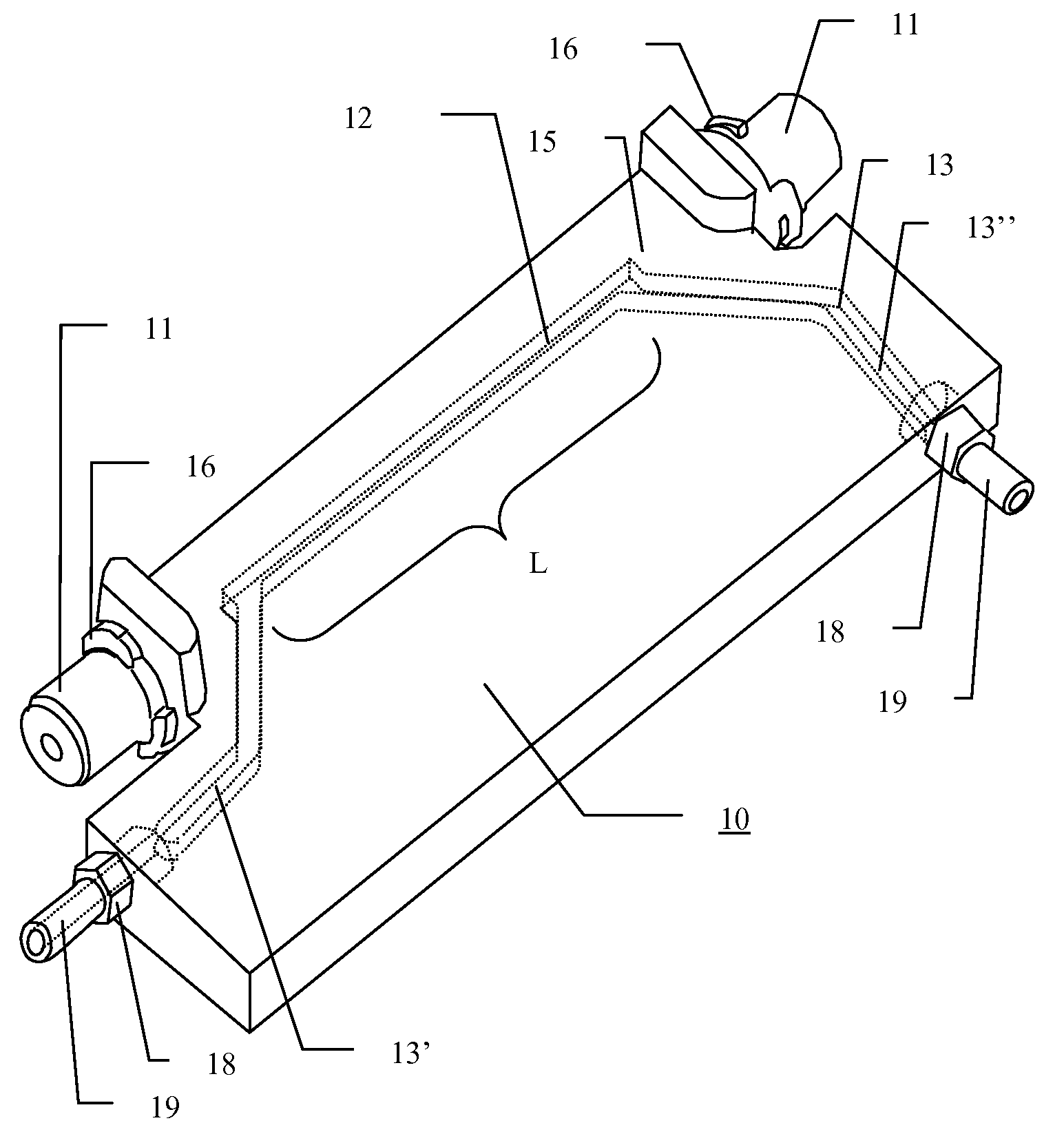
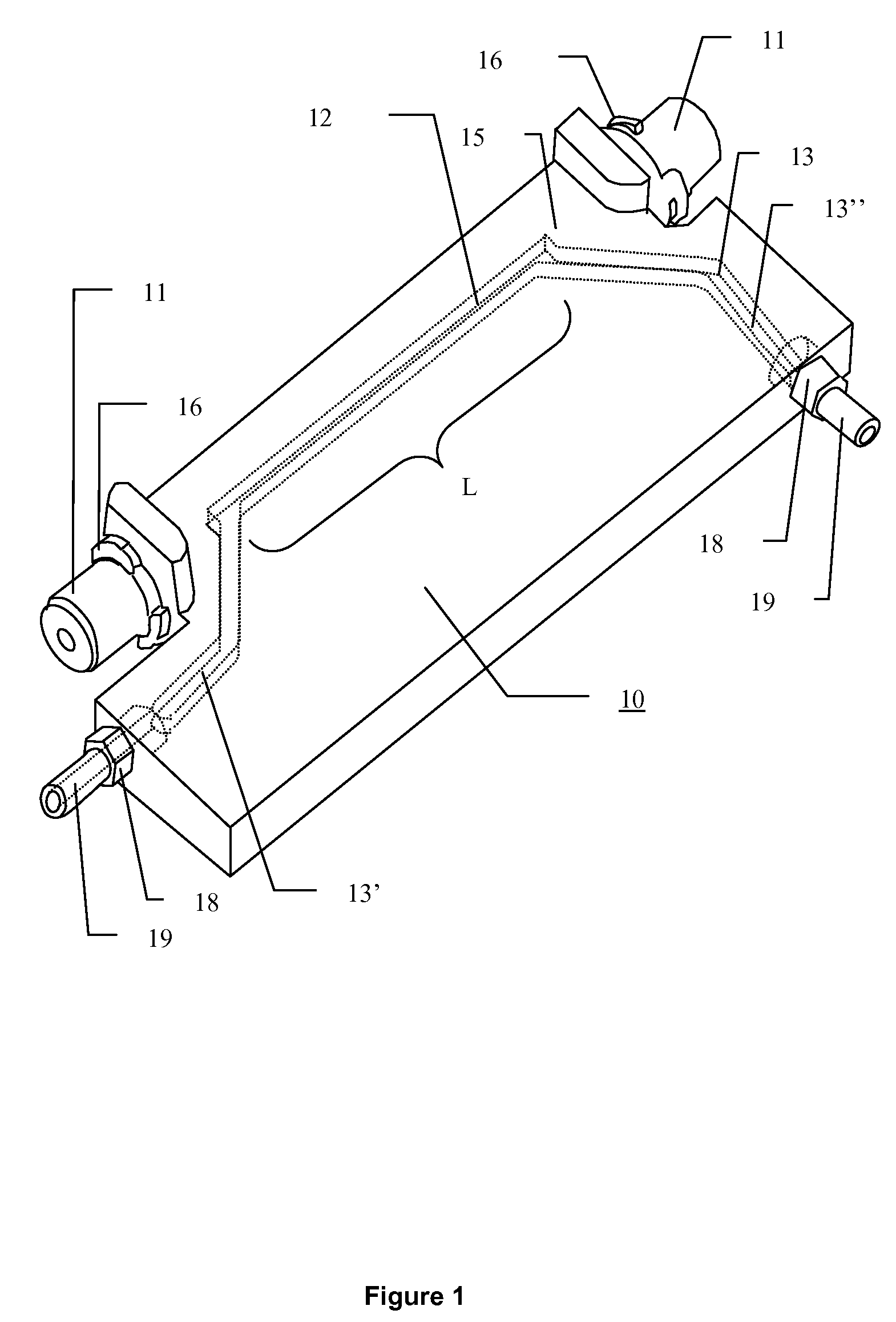
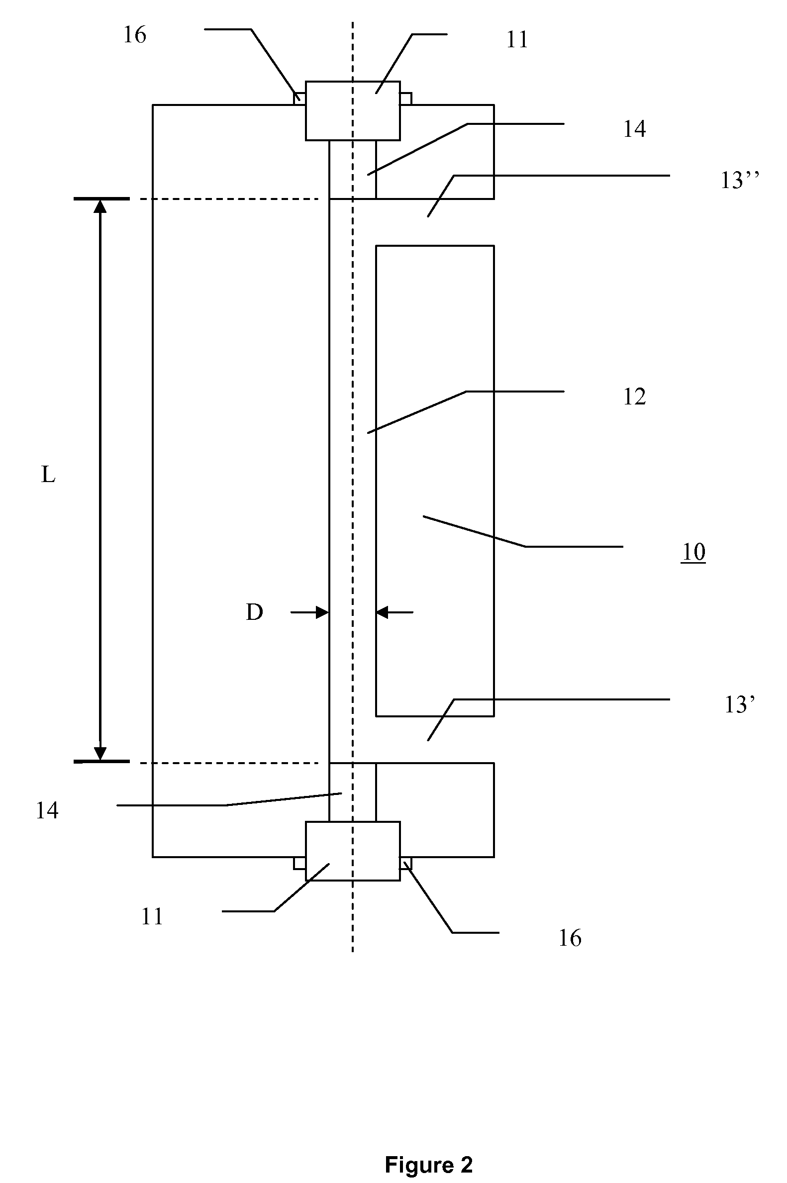
[0037]FIG. 2 is a schematic plan view of a flow cell (10) according to the present invention. The ultrasonic transducers (11) are positioned in alignment, opposite each other, separated by an essentially straight part (12) of a flow cell channel (13). The ultrasonic transducers (11) are positioned along the axis of the essentially straight part (12) of the flow cell channel (13). The ultrasonic transducers (11) are separated from the fluid inside the flow cell channel (13) by at least one plug (14), to ensure that the ultrasonic transducers (11) do not come in direct contact with the fluid inside the flow cell channel (13). The ultrasonic transducers (11) are detachable from the flow cell (10). The cross section of the channel (13) is typically shaped as a circle, but any geometry shape, for example a rectangle, should be considered to be within the scope of the present invention. In one embodiment of the present invention, the cross section of the channel (13) is shaped as a circle...
third embodiment
[0038]FIG. 3a) is an exploded perspective view of an ultrasonic flow meter according to the present invention. The figure shows ultrasonic transducers (11) and bayonet joints (16) for coupling to the flow cell (10) with plugs (14), connectors (18) for coupling of the flow cell (10) to another channel for liquid flow (19) and a sealing O-ring (20).
[0039]FIG. 3b) is a perspective view of the third embodiment of the ultrasonic flow meter according to the present invention. The figure shows ultrasonic transducers (11) and bayonet joints (16) for coupling to the flow cell (10), and connectors (18) for coupling of the flow cell (10) to another channel for liquid flow (19).
[0040]FIG. 3c) is a cross sectional view of the third embodiment of the ultrasonic flow meter according to the present invention. The figure shows a flow cell (10) with ultrasonic transducers (11) and bayonet joints (16) with plugs (14) for coupling to the essentially straight channel (12), and connectors (18) for coupli...
PUM
 Abstract
Description
Claims
Application Information
 - R&D
- Intellectual Property
- Life Sciences
- Materials
- Tech Scout
- Unparalleled Data Quality
- Higher Quality Content
- 60% Fewer Hallucinations
Browse by: Latest US Patents, China's latest patents, Technical Efficacy Thesaurus, Application Domain, Technology Topic, Popular Technical Reports.
© 2025 PatSnap. All rights reserved.Legal|Privacy policy|Modern Slavery Act Transparency Statement|Sitemap|About US| Contact US: help@patsnap.com


