Magneto generator

Active Publication Date: 2008-08-14
MITSUBISHI ELECTRIC CORP
View PDF24 Cites 8 Cited by
  • Summary
  • Abstract
  • Description
  • Claims
  • Application Information

AI Technical Summary

Benefits of technology

[0008]Accordingly, the present invention is intended to obviate the problems as referred to above, and has for its object to obtain a magneto generator which is capable of increasing a suppression force to suppress permanent magnets from being moved to an opening side of a flywheel with easy construction and at low cost.
[0012]According to a magneto generator of the present invention, it is possible to increase a suppression force to suppress permanent magnets from being moved to an opening side of a flywheel with easy construction and at low cost.

Problems solved by technology

That is, the movement in the circumferential direction of the permanent magnets is restricted by set portions that are formed on a circumferential side surface of the flywheel so as to protrude between adjacent permanent magnets, respectively, but there is no function to positively restrict the movement in the axial direction of the permanent magnets, so there is fear that the permanent magnets might be moved to an opening side of the flywheel due to an increase in the weight of the permanent magnets or an increase in external load (engine vibration, etc.).
As a result, the processing cost thereof becomes high, and the movement in the axial direction of the permanent magnets can be restricted by the plastically deformed engagement segments, but there is fear that the permanent magnets might be moved to the opening side of the flywheel, similar to the above-mentioned first patent document.

Method used


Image

  • Magneto generator
  • Magneto generator
  • Magneto generator

Examples


embodiment 1

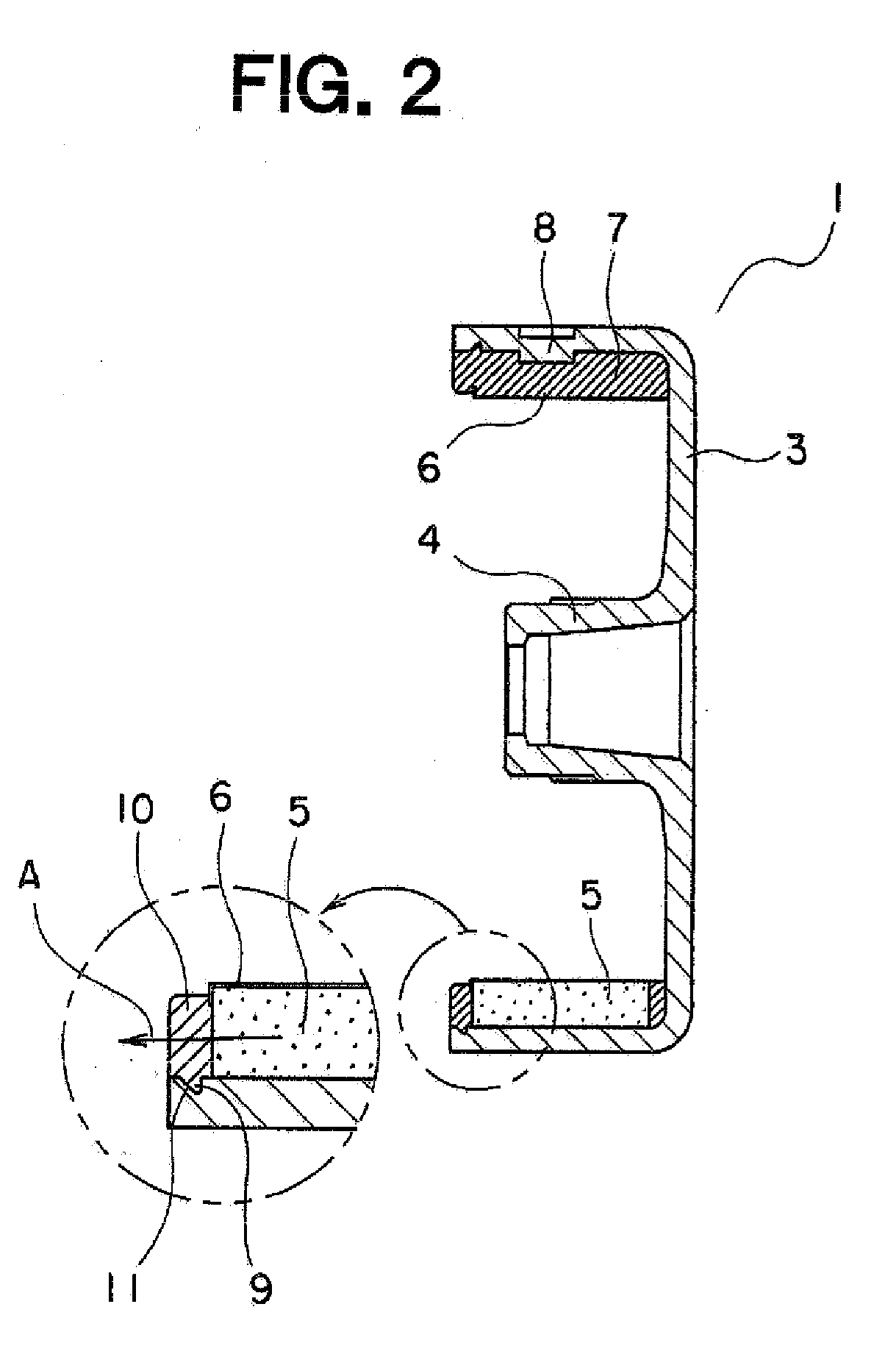
[0020]Referring to the drawings and first to FIG. 1, therein is shown, in a front elevational view, a magneto generator according to a first embodiment of the present invention. FIG. 2 is a cross sectional side elevational view that shows a rotor 1 of the magneto generator of FIG. 1.

[0021]This magneto generator is provided with the rotor 1 operatively connected with an internal combustion engine, and a stator 2 mounted on a bracket (not shown) arranged inside the rotor 1.

[0022]The rotor 1 includes a bowl-shaped flywheel 3 that has a boss portion 4 connected with a rotation shaft (not shown) which is driven to rotate by the internal combustion engine, permanent magnets 5 that are arranged on an inner peripheral wall surface of the flywheel 3 at intervals in a circumferential direction thereof, a magnet positioning member 7 that is made of resin and is arranged at an inner side of the permanent magnets 5 for positioning and fastening the permanent magnets 5 integrally with the flywhee...

embodiment 2

[0038]FIG. 4 is a cross sectional side elevational view that shows a rotor 30 of a magneto generator according to a second embodiment of the present invention.

[0039]In this second embodiment, a flywheel 31 has a collar portion 32 formed at an opening portion thereof so as to be bent over its entire perimeter along a circumferential direction at an inner diameter side.

[0040]A magnet positioning member 7 has a magnet coming-off preventing member 33 formed integrally therewith at the opening side of the flywheel 31 so as to be interposed between the collar portion 32 and the end faces of permanent magnets 5.

[0041]The other construction of this second embodiment is similar to that of the first embodiment.

[0042]In this embodiment, too, when a force in an axial direction (in a direction of arrow C in FIG. 4) acts on the permanent magnets 5, the force is mainly supported by a shearing stress generated in the collar portion 32, so the proof strength of the permanent magnets 5 resistant to t...

embodiment 3

[0044]FIG. 5 is a cross sectional side elevational view that shows a rotor 40 of a magneto generator according to a third embodiment of the present invention.

[0045]In this third embodiment, a cover protector 42 has a collar portion 43 formed on a peripheral end thereof at a side near an opening portion of a flywheel 41 so as to be bent toward a radially outer side and extend over its entire perimeter along a circumferential direction.

[0046]A magnet positioning member 7 has a magnet coming-off preventing member 44 formed integrally therewith at the opening side of the flywheel 41 so as to cover the end faces of permanent magnets 5. The collar portion 43 is embedded in the magnet coming-off preventing member 44.

[0047]The other construction of this third embodiment is similar to that of the first embodiment.

[0048]Here, note that the collar portion 43 may be intermittently or discontinuously formed in a circumferential direction.

[0049]In this third embodiment, too, when a force in an ax...


PUM


Abstract

A magneto generator can increase a suppression force to suppress permanent magnets from being moved to an opening side of a flywheel with easy construction and at low cost. In this magnet generator, the flywheel has a groove formed on its inner peripheral wall surface at an opening side thereof, and a magnet positioning member has a magnet coming-off preventing member formed at the opening side of the flywheel so as to cover end faces of the permanent magnets, with a protrusion being formed on the magnet coming-off preventing member so as to engage the groove in the flywheel. The protrusion is in engagement with the groove whereby the movement in an axial direction of the permanent magnets can be suppressed.

Description

BACKGROUND OF THE INVENTION[0001]1. Field of the Invention[0002]The present invention relates to a magneto generator which generates electricity under the electromagnetic induction action of permanent magnets and magneto coils in accordance with the rotation of a flywheel.[0003]2. Description of the Related Art[0004]In the past, there has been known a magneto generator which includes a bowl-shaped flywheel that rotates about an axis of rotation, a plurality of permanent magnets fixedly secured to an inner peripheral wall surface of the flywheel, a magnet positioning member made of a resin that is arranged at an inner side of the flywheel to position and fixedly secure the permanent magnets to the flywheel integrally therewith, a stator core that is arranged at an inner side of the permanent magnets and has a plurality of teeth protruding to a radially outer side, and a magneto coil that is formed of a conductor wound around each of the teeth (see, for example, a first patent documen...

Claims


Application Information

Patent Timeline
IPC IPC(8): H02K21/22
CPCH02K21/222H02K1/2786H02K1/2791
Inventor KIHARA, NOBUHIROIMAIZUMI, KAORU
Owner MITSUBISHI ELECTRIC CORP
Why Eureka
Try Eureka