Method for manufacturing stator for electric rotary machine

a technology of electric rotary machines and stators, which is applied in the manufacture of stator/rotor bodies, magnetic circuit shapes/forms/construction, transportation and packaging, etc., can solve the problems of design electric rotary machines, difficult to change ring resonance frequency, and no measures have been taken to reduce the resonance level

Active Publication Date: 2022-08-23
HONDA MOTOR CO LTD
View PDF7 Cites 0 Cited by
  • Summary
  • Abstract
  • Description
  • Claims
  • Application Information

AI Technical Summary

Benefits of technology

[0004]As described above, in order to improve the quietness of vehicles equipped with electric rotary machines, it is necessary to suppress the excitation force and resonance level of the electric rotary machines. Although the electric rotary machine described in JP-A-5-304742 suppresses the excitation force by preventing the magnetic vibration of the stator core from being transmitted, no measures have been taken to reduce the resonance level. However, since the resonance level of the electric rotary machine increases when the two resonance frequencies of ring resonance and bending resonance of the stator overlap each other, a measure for reducing the resonance level is also important to improve quietness.

Problems solved by technology

Although the electric rotary machine described in JP-A-5-304742 suppresses the excitation force by preventing the magnetic vibration of the stator core from being transmitted, no measures have been taken to reduce the resonance level.
It is difficult to change a ring resonance frequency in an already designed electric rotary machine because the shape and size of a stator affect the performance of the electric rotary machine.
However, changing the number of caulking points or changing the welding method in order to change the bending resonance frequency is not preferable because of large-scale remodeling of equipment and deterioration of efficiency such as iron loss of a electric rotary machine.

Method used


Image

  • Method for manufacturing stator for electric rotary machine
  • Method for manufacturing stator for electric rotary machine
  • Method for manufacturing stator for electric rotary machine

Examples


first embodiment

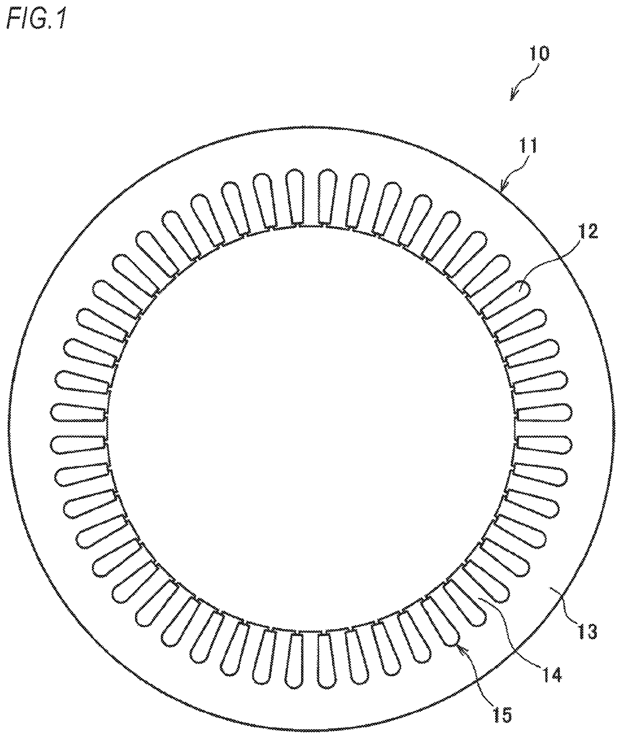
[0033]FIG. 1 is a radial sectional view of a stator of a electric rotary machine of an embodiment. A stator 10 shown in FIG. 1 is combined with a rotor (not shown) provided therein to constitute a electric rotary machine. The electric rotary machine is configured to rotate the rotor by energizing the coil 12 wound around the teeth 14 of the stator 10.

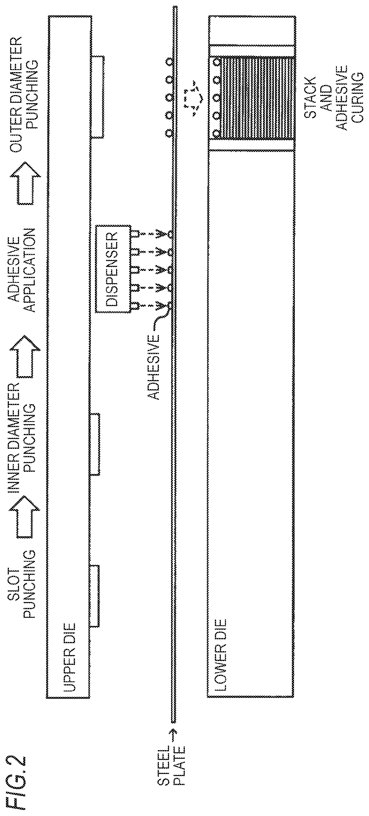
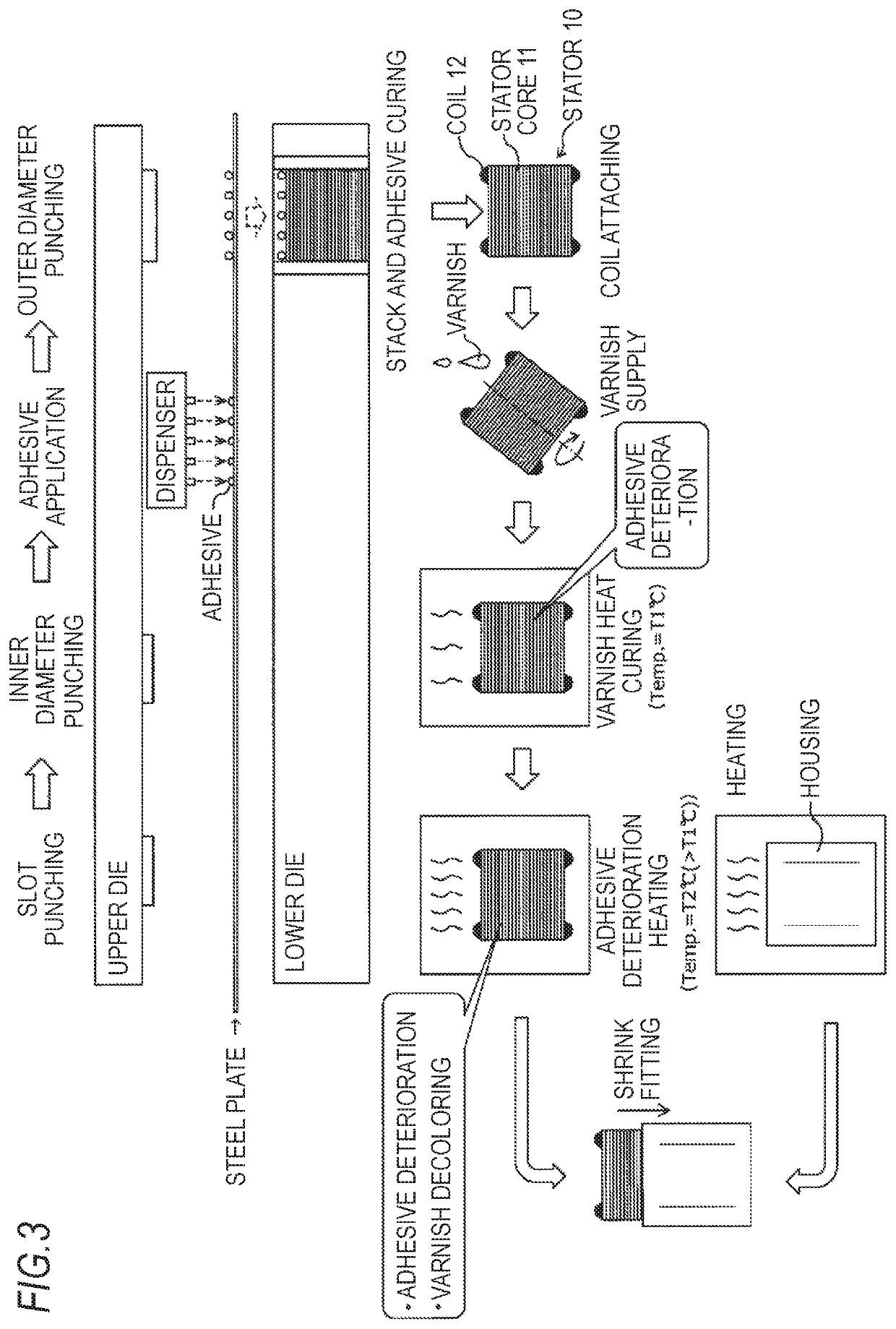
[0034]The stator 10 has a stator core 11 and a coil 12. The stator core 11 is formed by stacking a plurality of circular steel plates of approximately the same shape. When a steel plate is stacked, an adhesive is applied to a part of the surface of the steel plate to be opposed to the other steel plate. Therefore, a stator core 11 which is an aggregate of a plurality of steel plates stacked and fixed has a circular cylindrical shape.

[0035]Each steel plate constituting the stator core 11 is a plate-like member having an annular stator yoke 13, a plurality of teeth 14 projecting radially inward from the stator yoke 13 at equal intervals, ...

second embodiment

[0039]Similar to the first embodiment, a stator of s second embodiment is combined with a rotor (not shown) provided therein to constitute a electric rotary machine. The electric rotary machine is configured to rotate the rotor by energizing the coil wound around the teeth of the stator.

[0040]Similar to the stator 10 of the first embodiment shown in FIG. 1, the stator of the second embodiment includes a stator core 11 and a coil 12. The stator core 11 is formed by stacking a plurality of circular steel plates of approximately the same shape. When a steel plate is stacked, an adhesive is applied to a part of the surface of the steel plate to be opposed to the other steel plate. Therefore, a stator core 11 which is an aggregate of a plurality of steel plates stacked and fixed has a circular cylindrical shape.

[0041]Each steel plate constituting the stator core 11 is a plate-like member having an annular stator yoke 13, a plurality of teeth 14 projecting radially inward from the stator ...


PUM

PropertyMeasurementUnit
stack strengthaaaaaaaaaa
bending resonance frequencyaaaaaaaaaa
circular resonance frequencyaaaaaaaaaa

Abstract

A method for manufacturing a stator for an electric rotary machine including a stator core formed by stacking a plurality of steel plates and a coil attached to the stator core, the method includes forming the steel plates, forming the stator core by stacking and fixing the plurality of steel plates with an adhesive, attaching the coil to the stator core, and changing a stack strength of the stator core, by deteriorating the adhesive such that a bending resonance frequency of the stator does not overlap with a pre-measured circular resonance frequency of the stator, the bending resonance frequency varying depending on the stack strength of the plurality of steel plates.

Description

CROSS REFERENCE TO PRIOR APPLICATION[0001]This application is a National Stage Patent Application of PCT International Patent Application No. PCT / JP2018 / 010326 (filed on Mar. 15, 2018) under 35 U.S.C. § 371, which claims priority to Japanese Patent Application No. 2017-052174 (filed on Mar. 17, 2017), which are all hereby incorporated by reference in their entirety.TECHNICAL FIELD[0002]The present invention relates to a method for manufacturing a stator for an electric rotary machine.BACKGROUND ART[0003]In order to improve the quietness of vehicles equipped with electric rotary machines such as hybrid vehicles and electric vehicles, it is necessary to suppress the excitation force and resonance level of the electric rotary machines. An electric rotary machine described in JP-A-5-304742 has a structure of preventing the magnetic vibration of a stator core from being transmitted to a stator frame (housing), which realizes low vibration.SUMMARY OF INVENTION[0004]As described above, in ...

Claims


Application Information

Patent Timeline
Patent Type & Authority Patents(United States)
IPC IPC(8): H02K15/02H02K15/12H02K1/16H02K15/14H02K15/00
CPCH02K15/024H02K1/165H02K15/12H02K15/14H02K15/00H02K15/0025H02K2201/09Y10T29/49009Y02T10/64
Inventor SAKURADA, MANABUNOMURA, SHOGO
Owner HONDA MOTOR CO LTD
Why Eureka
Try Eureka