Display device

a display device and reflective sheet technology, applied in the field of display devices, can solve problems such as the problem of reflective sheet flexion, and achieve the effect of suppressing the reflective sheet due to the environmental temperature around the display devi

Active Publication Date: 2018-10-30
MAXELL HLDG LTD
View PDF27 Cites 0 Cited by
  • Summary
  • Abstract
  • Description
  • Claims
  • Application Information

AI Technical Summary

Benefits of technology

[0008]One or more embodiments of the present invention provide a display device that can suppress a reflective sheet from flexing due to the environmental temperature around the display device.
[0010]According to one or more embodiments, the opening may be provided on the position corresponding to the peripheral portion of the light guide plate, and the first fixing part of the back surface enclosure interposes between the supporting member the peripheral portion of the light guide plate exposed though the opening. A gap may thereby be formed between the reflective sheet and the light guide plate near the opening of the reflective sheet, and a force that fixes the reflective sheet on the light guide plate may become comparatively small near the opening of the reflective sheet. As a result, when the back surface enclosure is formed of resin, for example, the second fixing part suppresses the reflective sheet from being pulled even when the back surface enclosure expands or contracts according to an environmental temperature around the display device, and flexion of the reflective sheet can therefore be suppressed from occurring.
[0014]According to one or more embodiments, the reflective sheet may be fixed with a comparatively large force to the light guide plate in a location where the fastening member mutually fastens the supporting member and the back enclosure. Because of this, a force with which the second fixing part pulls the reflective sheet becomes comparatively large near the placement location of the fastening member when the back surface enclosure expands or contracts according to the environmental temperature around the display device. According to one or more embodiments, the first fixing part can effectively suppress the force with which the second fixing part pulls the reflective sheet when the back enclosure expands or contracts according to the environmental temperature around the display device because the first fixing part is disposed to correspond with such placement location of the fastening member.
[0021]According to the display device according to one or more embodiments of the present invention, flexion of the reflective sheet due to the environmental temperature around the display device can be suppressed.

Problems solved by technology

However, generally, resin has a property of expanding in a comparatively high environmental temperature and shrinking in a comparatively low environmental temperature.
As a result, there is concern of flexion occurring in the reflective sheet.

Method used


Image

  • Display device
  • Display device
  • Display device

Examples


first example

[0030](First Example)

[0031][Overall Configuration of the Display Device]

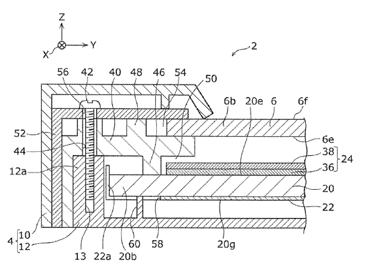
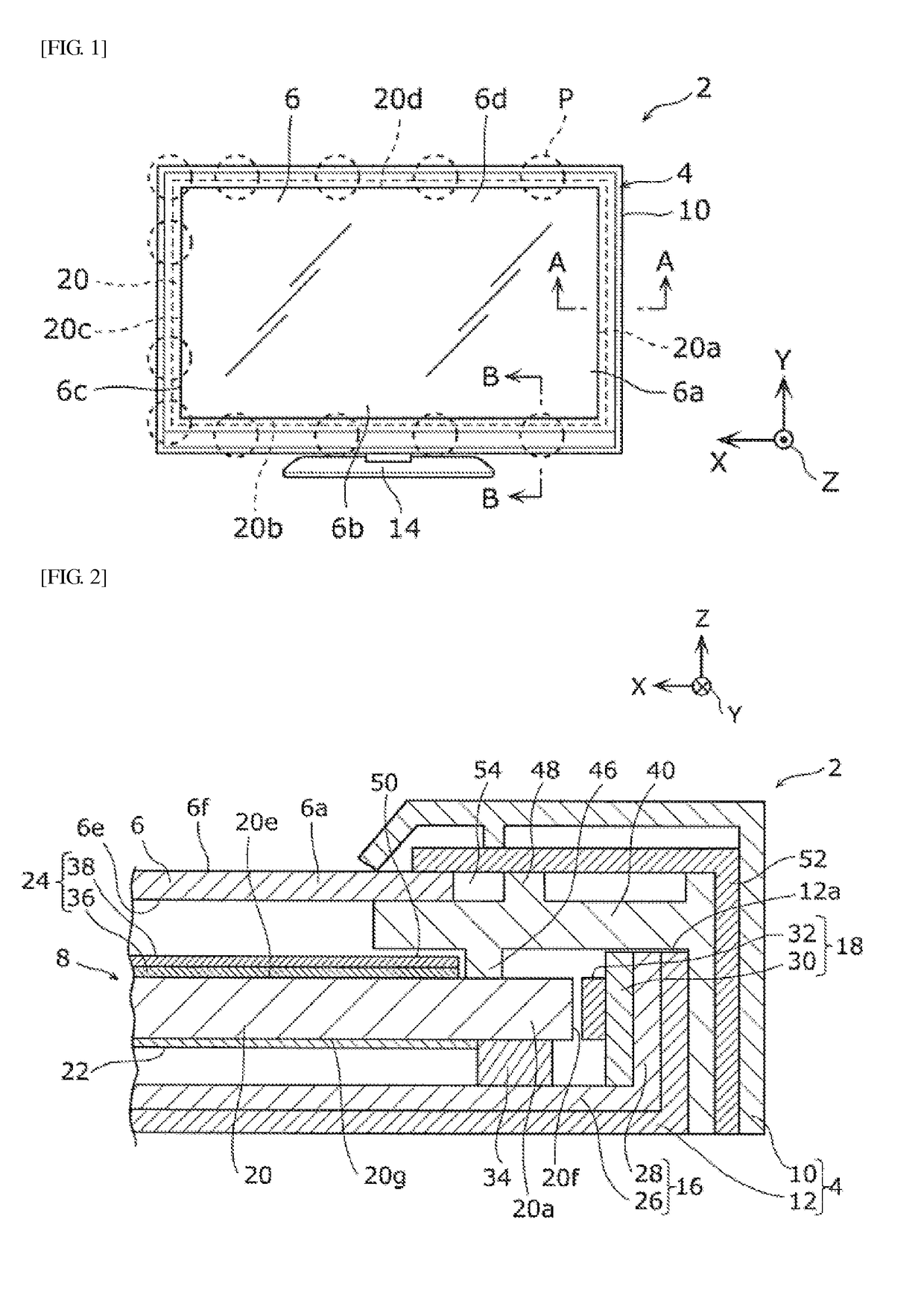
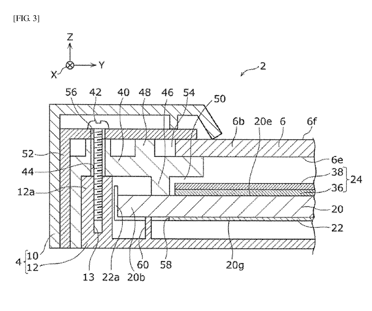
[0032]First, an overall configuration of the display device according to one or more embodiments of a first example of the present invention will be described with reference to FIGS. 1 to 4. FIG. 1 is a diagram illustrating a front surface side of the display device according to one or more embodiments of the first example. FIG. 2 is a partial cross-sectional view of the display device cut along the line A-A in FIG. 1. FIG. 3 is a partial cross-sectional view of the display device cut along the line B-B in FIG. 1. FIG. 4 is a partial cross-sectional perspective view of the display device cut along the line B-B in FIG. 1. A front cabinet 10 and a bezel 52 described below are not illustrated in FIG. 4 for convenience in the description.

[0033]As illustrated in FIGS. 1 and 2, a display device 2 is provided with an enclosure 4, a liquid crystal panel 6 (configuring a display panel) provided inside the enclosure 4, an...

second example

[0059](Second Example)

[0060]Next, a configuration of a display device according to one or more embodiments of a second example will be described with reference to FIG. 7. FIG. 7 is a partial cross-sectional exploded perspective view illustrating an exploded portion of the display device according to one or more embodiments of the second example. According to one or more embodiments of the second example, the same reference numerals will be attached to the same or similar components as the first example described above, and explanations thereof will be omitted.

[0061]As illustrated in FIG. 7, in a display device 2A according to one or more embodiments of the second example, a plurality of openings 58A provided on the reflective sheet 22A is configured from rectangular through holes. The plurality of openings 58A is disposed near an end portion 22Aa of the reflective sheet 22A.

[0062]Furthermore, a plurality of first fixing parts 60A and a plurality of second fixing parts 62A are each c...


PUM

PropertyMeasurementUnit
thicknessaaaaaaaaaa
thicknessaaaaaaaaaa
height H2aaaaaaaaaa

Abstract

A display device includes a display panel, a light source that emits light, a light guide plate comprising a lateral surface that receives the light, wherein the light source emits the light to the lateral surface from a main surface to a back surface of the display panel, a supporting member provided between a peripheral portion of the display panel and a peripheral portion of the light guide plate and that supports the peripheral portion of the display panel, a reflective sheet disposed so as to cover a back surface on an opposite side of the main surface of the light guide plate and that comprises an opening at a position corresponding to the peripheral portion of the light guide plate, and a back surface enclosure disposed so as to oppose the reflective sheet and that includes a first fixing part and a second fixing part.

Description

TECHNICAL FIELD[0001]The present invention relates to a display device for displaying images.BACKGROUND TECHNOLOGY[0002]A display device provided with a backlight unit of an edge light type that irradiates light toward a back surface of a display panel, such as, for example, a liquid crystal television receiver or the like, is known (for example, see Patent Document 1).[0003]This backlight unit of the edge light type is provided with a light guide plate, a light emitting diode (LED) bar, and a reflective sheet. The light guide plate is disposed so as to oppose the back surface of the display panel. The LED bar has a wiring substrate and a plurality of LEDs mounted to the wiring substrate. This LED bar is disposed so as to oppose a lateral surface of the light guide plate. The reflective sheet is disposed so as to cover a back surface of the light guide plate.[0004]The backlight unit described above is provided inside an enclosure. The enclosure has a frame-like front cabinet that co...

Claims


Application Information

Patent Timeline
Patent Type & Authority Patents(United States)
IPC IPC(8): G02F1/1333F21V8/00G02F1/1335
CPCG02B6/0085G02B6/0088
Inventor NAKANO, KODAISUDO, TATSUJI
Owner MAXELL HLDG LTD
Why Eureka
Try Eureka