
Multimodal memory controllers

a memory controller and multi-modal technology, applied in the field of design structure, can solve the problems of limiting the bandwidth of single-ended signaling system, interference, or crosstalk between signals, and computer systems that have evolved into extremely complex devices

Inactive Publication Date: 2008-08-07
IBM CORP
View PDF6 Cites 22 Cited by
  • Summary
  • Abstract
  • Description
  • Claims
  • Application Information

AI Technical Summary

Benefits of technology

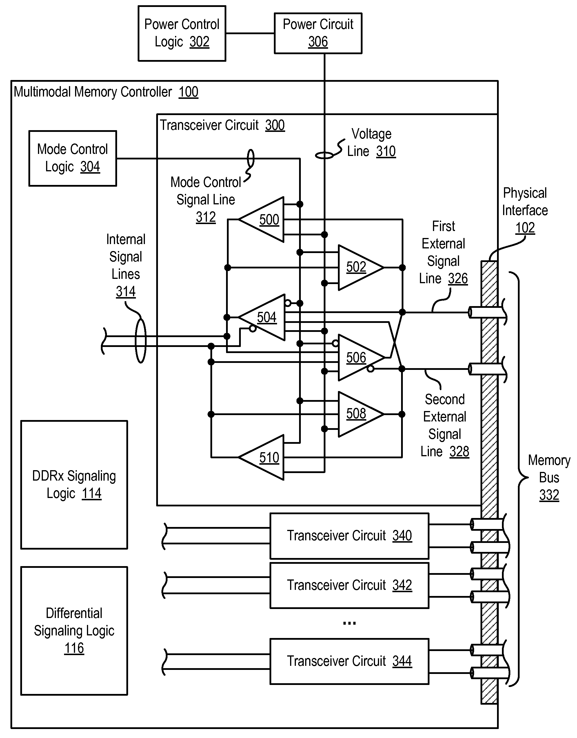
[0009]Design structures embodied in machine readable medium are provided. Embodiments of the design structures include a multimodal memory controller comprising: a transceiver circuit having at least one internal signal line, a first external signal line, a second external signal line, and a mode control signal line, the mode control signal line having asserted upon it a mode control signal, and the transceiver circuit configured to operate the external signal lines for single-ended signaling at a first voltage

Problems solved by technology

Since that time, computer systems have evolved into extremely complicated devices.
The main disadvantage of single-ended signaling is that the return currents for all the signals share the same wire and can sometimes cause interference, or crosstalk, between the signals.
Such crosstalk typically limits the bandwidth of single-ended signaling systems.
The drawback to having these two computer memory bus architectures is that system designers must design and manufacture memory controllers with separate physical interfaces—one physical interface to drive a computer memory bus that implements a parallel, single-ended signaling protocol, and another physical interface to drive a computer memory bus that implements a serial, differential signaling protocol.
Designing and manufacturing each of these separate components for the two architectures is time-consuming and costly.

Method used


Image

  • Multimodal memory controllers
  • Multimodal memory controllers
  • Multimodal memory controllers

Examples


Embodiment Construction

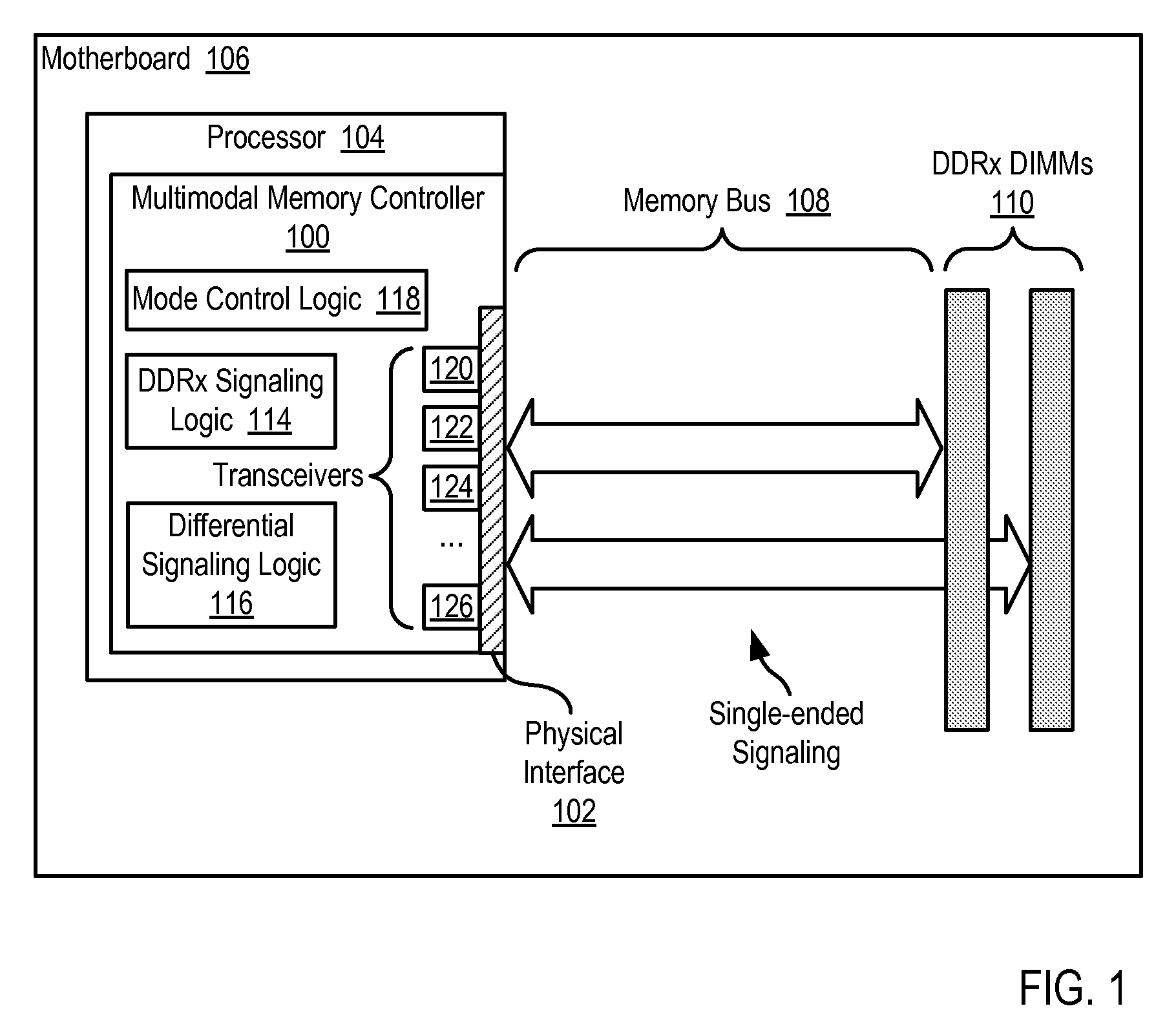
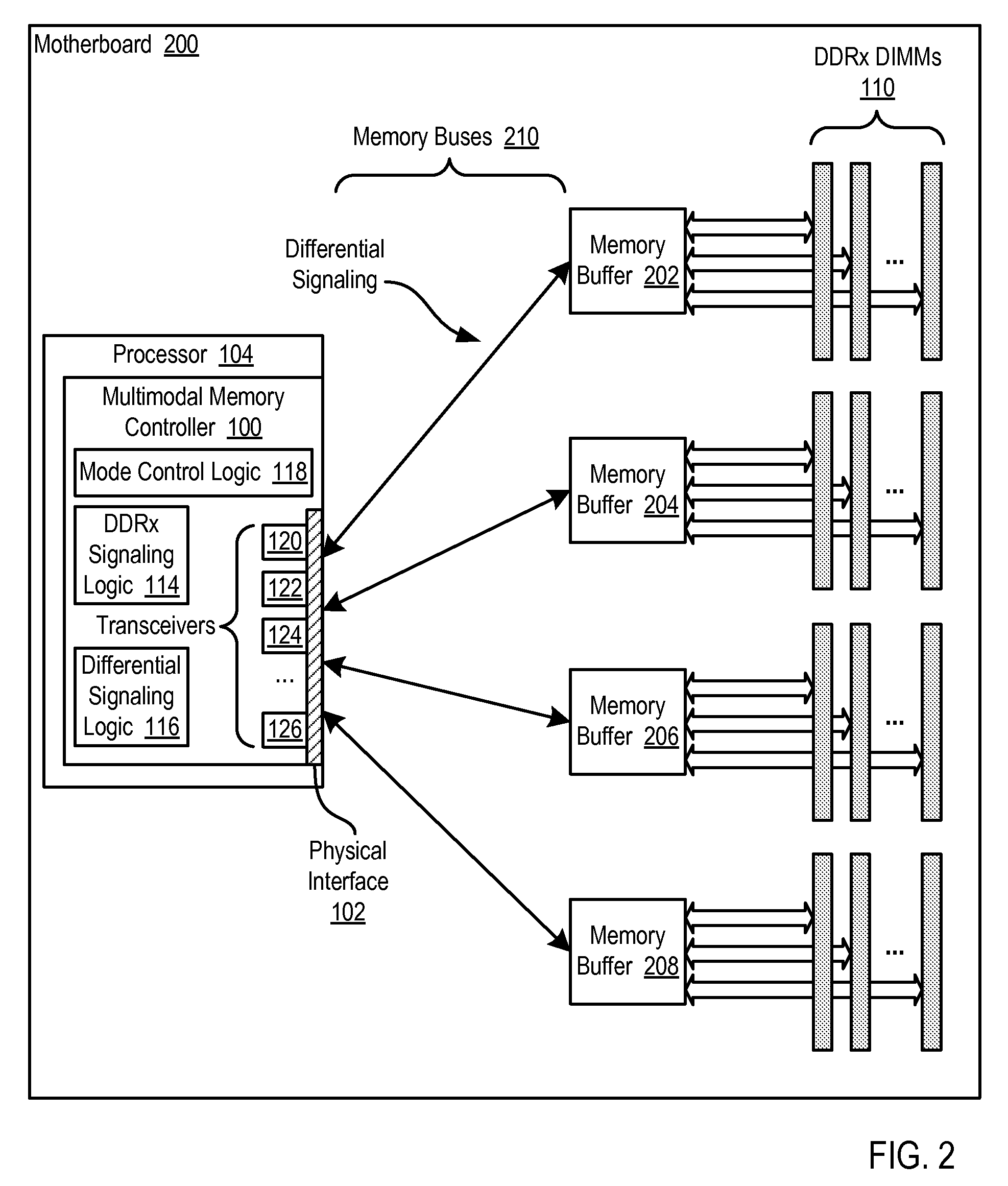
[0020]Exemplary multimodal memory controllers and exemplary methods for multimodal operation of a memory controller in accordance with the present invention are described with reference to the accompanying drawings, beginning with FIG. 1. FIG. 1 sets forth a block diagram of automated computing machinery that includes an exemplary multimodal memory controller (100) according to embodiments of the present invention. The multimodal memory controller (100) of FIG. 1 is integrated into a computer processor (104) installed on motherboard (106). Although the multimodal memory controller (100) of FIG. 1 is integrated in the processor (104), readers will note that such an implementation is for explanation and not for limitation. In fact, multimodal memory controllers according to embodiments of the present invention may be implemented as a standalone semiconductor device that connect to a system processor, as part of a bus adapter such as, for example, the Intel Northbridge, or any other im...


PUM


Abstract

Design structures embodied in machine readable medium are provided. Embodiments of the design structures include a multimodal memory controller comprising: a transceiver circuit having at least one internal signal line, a first external signal line, a second external signal line, and a mode control signal line, the mode control signal line having asserted upon it a mode control signal, and the transceiver circuit configured to operate the external signal lines for single-ended signaling at a first voltage when the mode control signal is a first value and to operate the external signal lines for differential signaling at a second voltage when the mode control signal is a second value.

Description

CROSS-REFERENCE TO RELATED APPLICATION[0001]This application is a continuation-in-part application of and claims priority from U.S. patent application Ser. No. 11 / 567,549, filed on Dec. 6, 2006.BACKGROUND OF THE INVENTION[0002]1. Field of the Invention[0003]The field of the invention is related to a design structure, and more specifically to a design structure for multimodal memory controllers.[0004]2. Description of Related Art[0005]The development of the EDVAC computer system of 1948 is often cited as the beginning of the computer era. Since that time, computer systems have evolved into extremely complicated devices. Today's computers are much more sophisticated than early systems such as the EDVAC. Computer systems typically include a combination of hardware and software components, application programs, operating systems, processors, buses, memory, input / output devices, and so on. As advances in semiconductor processing and computer architecture push the performance of the compu...

Claims


Application Information

Patent Timeline
IPC IPC(8): G06F13/14G06F12/00
CPCG06F13/1694
Inventor DREPS, DANIEL M.MCCREDIE, BRADLEY D.
Owner IBM CORP
Learn More