Method for the Continuous Implementation of Polymerisation Processes

Active Publication Date: 2008-08-07
LIST TECHNOLOGY AG +1
View PDF12 Cites 20 Cited by
  • Summary
  • Abstract
  • Description
  • Claims
  • Application Information

AI Technical Summary

Benefits of technology

[0004]In order to allow the amputee athlete to attain a higher level of performance, there is a need for a high performance prosthetic foot having improved applied mechanics, which foot can out perform the human foot and also out perform the prior art prosthetic feet. It is of interest to the amputee athlete to have a high performance prosthetic foot having improved applied mechanics, high low dynamic response, and alignment adjustability that can be fine tuned to improve the horizontal and vertical components of activities which can be task specific in nature.
[0006]The adjustable fastening arrangement permits adjustment of the alignment of the calf shank and the foot keel with respect to one another in the longitudinal direction of the foot keel for tuning the performance of the prosthetic foot. By adjusting the alignment of the opposed upwardly arched midfoot portion of the foot keel and the downward convexly curved lower end of the calf shank with respect to one another in the longitudinal direction of the foot keel, the dynamic response characteristics and motion outcomes of the foot are changed to be task specific in relation to the needed / desired horizontal and vertical linear velocities. A multi-use prosthetic foot is disclosed having high and low dynamic response capabilities, as well as biplanar motion characteristics, which improve the functional outcomes of amputees participating in sporting and / or recreational activities. A prosthetic foot especially for sprinting is also disclosed.
[0007]The prosthetic foot can also include a device to limit the extent of the motion of the upper end of the calf shank in response to force loading and unloading the calf shank during use of the prosthetic foot. In one embodiment, the device is a piston-cylinder unit connected between the upper and lower ends of the calf shank and containing at least one pressurized fluid to limit the extent of motion and also dampen the energy being stored or released during calf shank compression and expansion. In other embodiments the posterior calf device stores its own potential energy during force loading of the prosthesis and returns the stored energy during force unloading to add to the total elastic energy storage capabilities thereby increasing the kinetic power generated for propulsive force by the prosthetic foot in gait.

Problems solved by technology

However, the dynamic response characteristics of this known artificial foot are limited.

Method used


Image

  • Method for the Continuous Implementation of Polymerisation Processes
  • Method for the Continuous Implementation of Polymerisation Processes
  • Method for the Continuous Implementation of Polymerisation Processes

Examples


Embodiment Construction

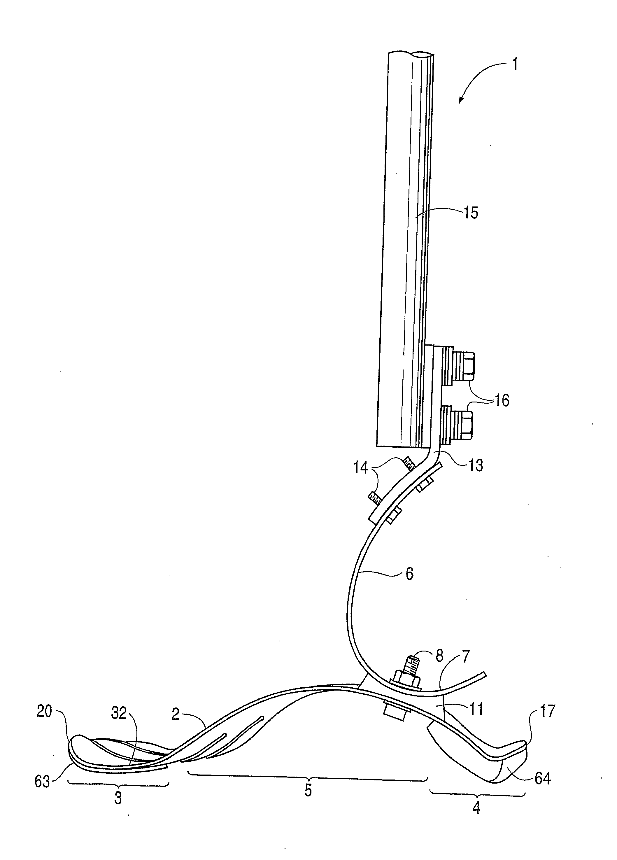
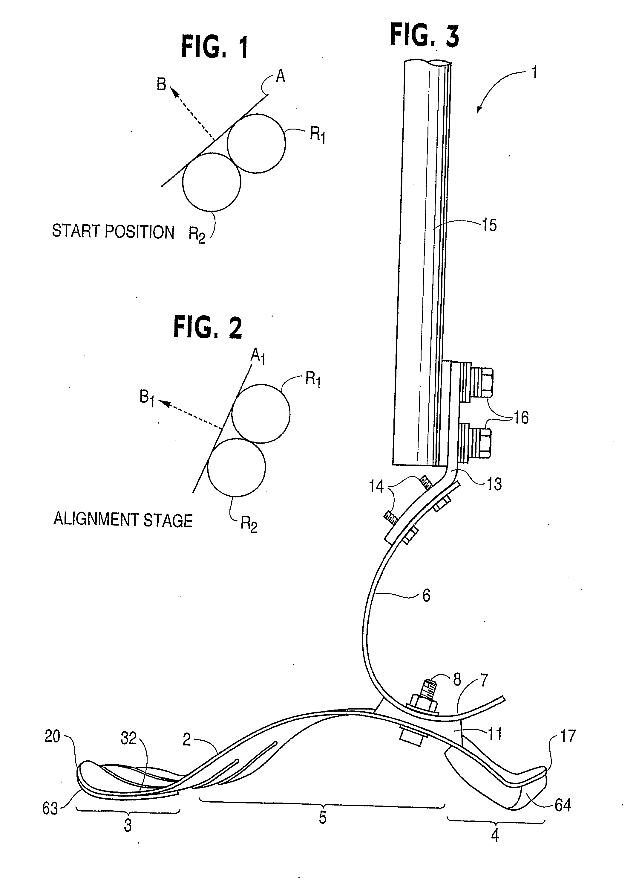
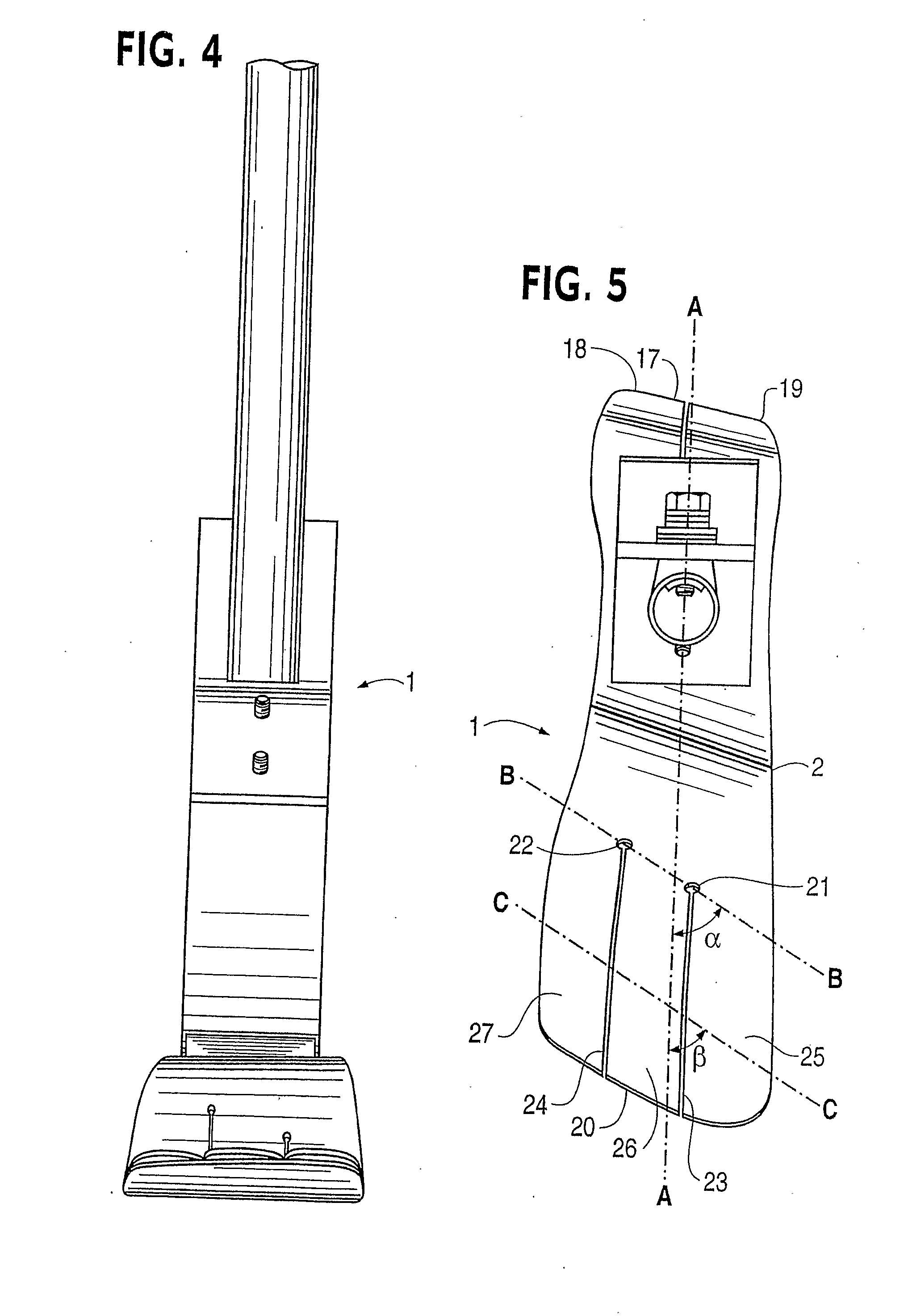
[0063]Referring now to the drawings, a prosthetic foot 1 in the example embodiment of FIGS. 3-5 is seen to comprise a longitudinally extending foot keel 2 having a forefoot portion 3 at one end, a hindfoot portion 4 at an opposite end and an upwardly arched midfoot portion 5 extending between the forefoot and hindfoot portions. The midfoot portion 5 is upward convexly curved over its entire longitudinal extent between the forefoot and hindfoot portions in the example embodiment.

[0064]An upstanding calf shank 6 of the foot 1 is attached at a portion of a downward convexly curved lower end 7 thereof to a proximate, posterior surface of the keel midfoot portion 5 by way of a releasable fastener 8 and coupling element 11. The fastener 8 is a single bolt with nut and washers in the example embodiment, but could be a releasable clamp or other fastener for securely positioning and retaining the calf shank on the foot keel when the fastener is tightened.

[0065]A longitudinally extending open...


PUM

PropertyMeasurementUnit
Lengthaaaaaaaaaa
Forceaaaaaaaaaa
Poweraaaaaaaaaa

Abstract

A prosthetic foot (124) incorporates a foot keel (165) and a calf shank (126) connected to the foot keel to form an ankle joint area of the prosthetic foot. A device (125) connected between the upper end of the calf shank and the lower portion of the prosthesis can be used to assist posterior movement of the upper end of a calf shank and control anterior movement of the upper end of the calf shank during use of the prosthesis. The device (125) has springs which store energy during force loading with anterior motion of the upper end of the calf shank in gait and which, during force unloading, return the stored energy as kinetic power for adding to the propulsive force on the user's body generated by the prosthesis in gait.

Description

TECHNICAL FIELD[0001]The present invention relates to a high performance prosthetic foot providing improved dynamic response capabilities as these capabilities relate to applied force mechanics.BACKGROUND ART[0002]A jointless artificial foot for a leg prosthesis is disclosed by Martin et al. in U.S. Pat. No. 5,897,594. Unlike earlier solutions wherein the artificial foot has a rigid construction provided with a joint in order to imitate the function of the ankle, the jointless artificial foot of Martin et al. employs a resilient foot insert which is arranged inside a foot molding. The insert is of approximately C-shaped design in longitudinal section, with the opening to the rear, and takes up the prosthesis load with its upper C-limb and via its lower C-limb transmits that load to a leaf spring connected thereto. The leaf spring as seen from the underside is of convex design and extends approximately parallel to the sole region, forward beyond the foot insert into the foot-tip regi...

Claims


Application Information

Patent Timeline
IPC IPC(8): A61F2/66A61F2/00A61F2/50A61F2/60A61F2/76
CPCB01F5/104C08F2/02B01F13/1027B01F15/0289B01J8/10B01J19/0066B01J2219/00033B01J2219/0004B01J2219/00108B01J2219/00128B01J2219/00168B01J2219/0025B01J2219/00272B01J2219/182B01F7/048B01F25/52B01F27/707B01F33/821B01F35/754551
Inventor FLEURY, PIERRE-ALAINISENSCHMID, THOMASLIECHTI, PIERRE
Owner LIST TECHNOLOGY AG
Why Eureka
Try Eureka