
Methods and apparatus for determining optimal RF transmitter placement via a coverage metric

Inactive Publication Date: 2008-07-31
SYMBOL TECH INC
View PDF4 Cites 14 Cited by
  • Summary
  • Abstract
  • Description
  • Claims
  • Application Information

AI Technical Summary

Benefits of technology

[0006]This summary is provided to introduce a selection of concepts in a simplified form that are further described below in the detailed description. This summary is not intended to identify key features or essential features of the claimed subject matter, nor is it intended to be used as an aid in determining the scope of the claimed subject matter.

Problems solved by technology

Because many different RF transmitters and other components may exist in a particular environment, the deployment and management of such systems can be difficult and time-consuming.
Such systems are unsatisfactory in a number of respects, however, as they fall short of the requirements due to the presence of gaps and holes.

Method used


Image

  • Methods and apparatus for determining optimal RF transmitter placement via a coverage metric
  • Methods and apparatus for determining optimal RF transmitter placement via a coverage metric
  • Methods and apparatus for determining optimal RF transmitter placement via a coverage metric

Examples


Embodiment Construction

[0012]The present invention relates to a method for optimizing the placement of RF components within an environment to maximize RF coverage. In this regard, the following detailed description is merely illustrative in nature and is not intended to limit the embodiments of the invention or the application and uses of such embodiments. Furthermore, there is no intention to be bound by any expressed or implied theory presented in the preceding technical field, background, brief summary or the following detailed description.

[0013]Embodiments of the invention may be described herein in terms of functional and / or logical block components and various processing steps. It should be appreciated that such block components may be realized by any number of hardware, software, and / or firmware components configured to perform the specified functions. For example, an embodiment of the invention may employ various integrated circuit components, e.g., memory elements, digital signal processing eleme...


PUM


Abstract

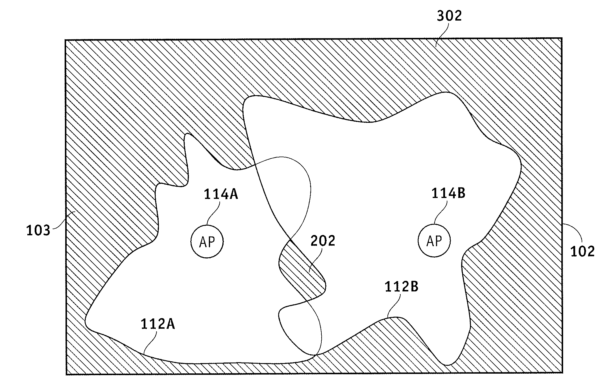
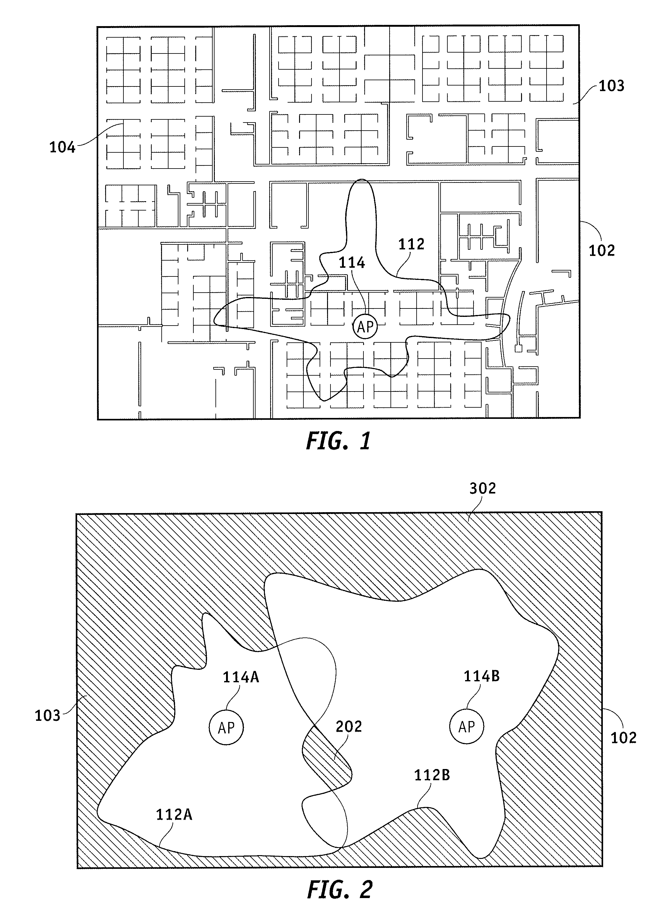
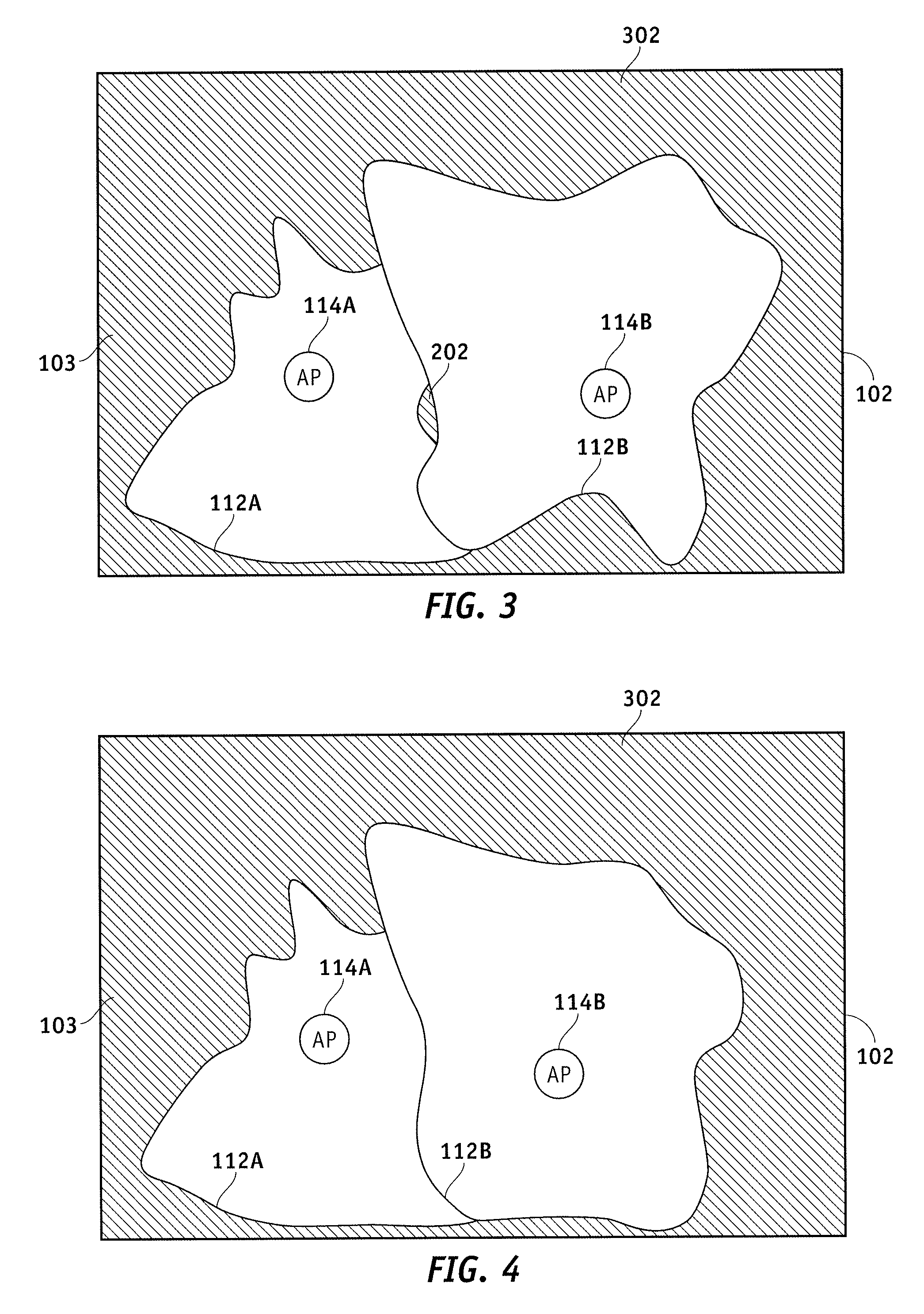
Systems and methods are provided for optimizing the placement of RF components within an environment. The system operates by defining a spatial model associated with the environment, determining a first placement location of the RF device within the spatial model, determining a coverage area associated with the RF device, identifying a set of gaps associated with the coverage area, calculating a coverage metric based on the set of gaps, determining a second placement location of the RF device within the spatial model based on the coverage metric, and placing the AP in the second placement location within the environment if the coverage metric is less than or equal to a predetermined threshold.

Description

TECHNICAL FIELD[0001]The present invention relates to wireless local area networks (WLANs) and other networks incorporating RF elements and / or RF devices. More particularly, the present invention relates to methods for automating the placement of RF devices, such as access points, within an environment.BACKGROUND[0002]There has been a dramatic increase in demand for mobile connectivity solutions utilizing various wireless components and WLANs. This generally involves the use of wireless access points that communicate with mobile devices using one or more RF channels (e.g., in accordance with one or more of the IEEE 802.11 standards).[0003]At the same time, RFID systems have achieved wide popularity in a number of applications, as they provide a cost-effective way to track the location of a large number of assets in real time. In large-scale applications such as warehouses, retail spaces, and the like, many RFID tags may exist in the environment. Likewise, multiple RFID readers are t...

Claims


Application Information

Patent Timeline
IPC IPC(8): H04Q7/36H04W16/20
CPCH04W16/20
Inventor LE, VINHHINSZ, CHRIS
Owner SYMBOL TECH INC
Learn More