Development apparatus
a technology of development apparatus and development plate, which is applied in the direction of electrographic process apparatus, instruments, optics, etc., can solve the problems of deteriorating the function of the apparatus, increasing the scattering of developers, and not always forming excellent images, so as to achieve no density variation or unevenness, and suppress thermal deformation
- Summary
- Abstract
- Description
- Claims
- Application Information
AI Technical Summary
Benefits of technology
Problems solved by technology
Method used
Image

Examples
first embodiment
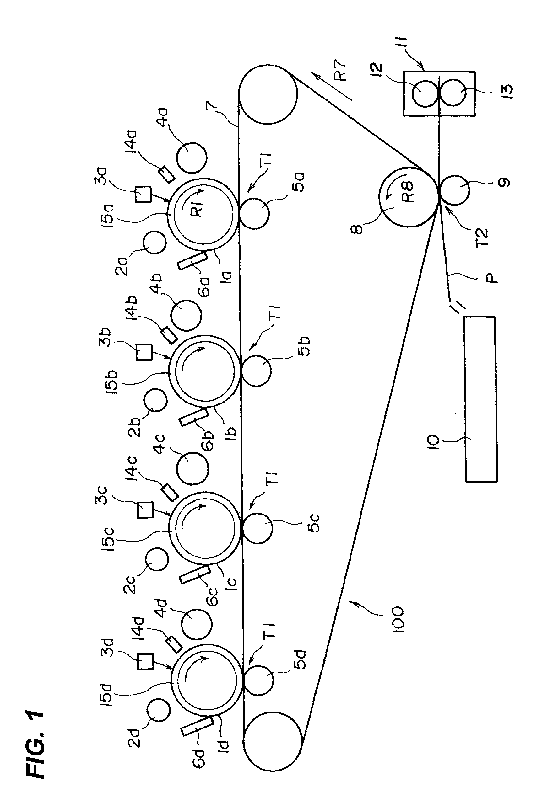
[0029]A first embodiment of the development apparatus of the present invention will be described using the drawings. FIG. 1 is a diagram illustrating a structure of an image forming apparatus according to the first embodiment. This embodiment is one mode to which the present invention can be applied, and the invention is not limited to the embodiment.
(Image forming apparatus 100)
[0030]As shown in FIG. 1, an image forming apparatus 100 is a four full-color electrophotographic system image forming apparatus having four image forming portions (image forming stations). The four image forming portions are disposed from upstream to downstream along a rotation direction (direction of arrow R7) of an intermediate transfer belt 7 as an intermediate transfer member.
[0031]Each image forming portion includes drum-shaped electrophotographic photosensitive members (“photosensitive drums”, hereinafter) 1a, 1b, 1c and 1d as image bearing members. The photosensitive drums 1a to 1d form yellow, magen...
second embodiment
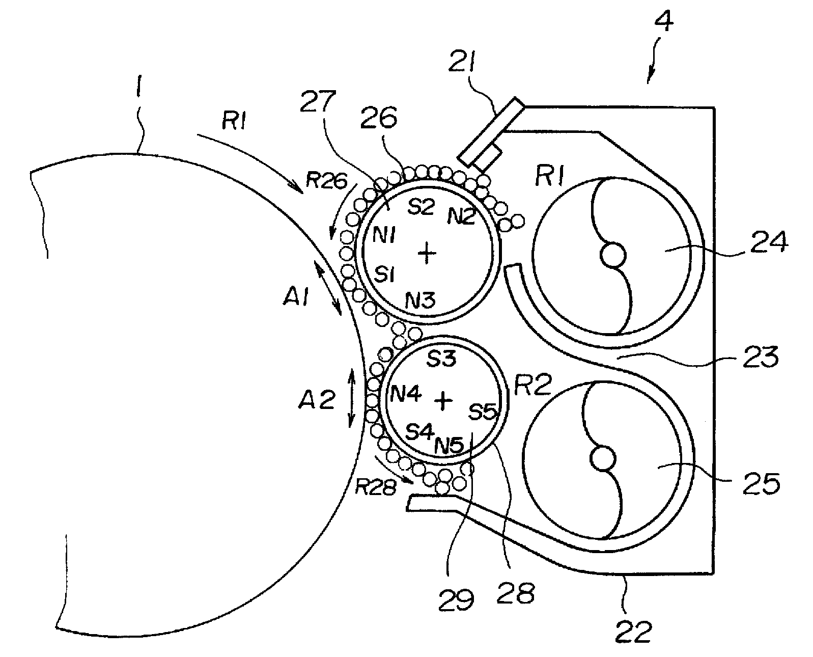
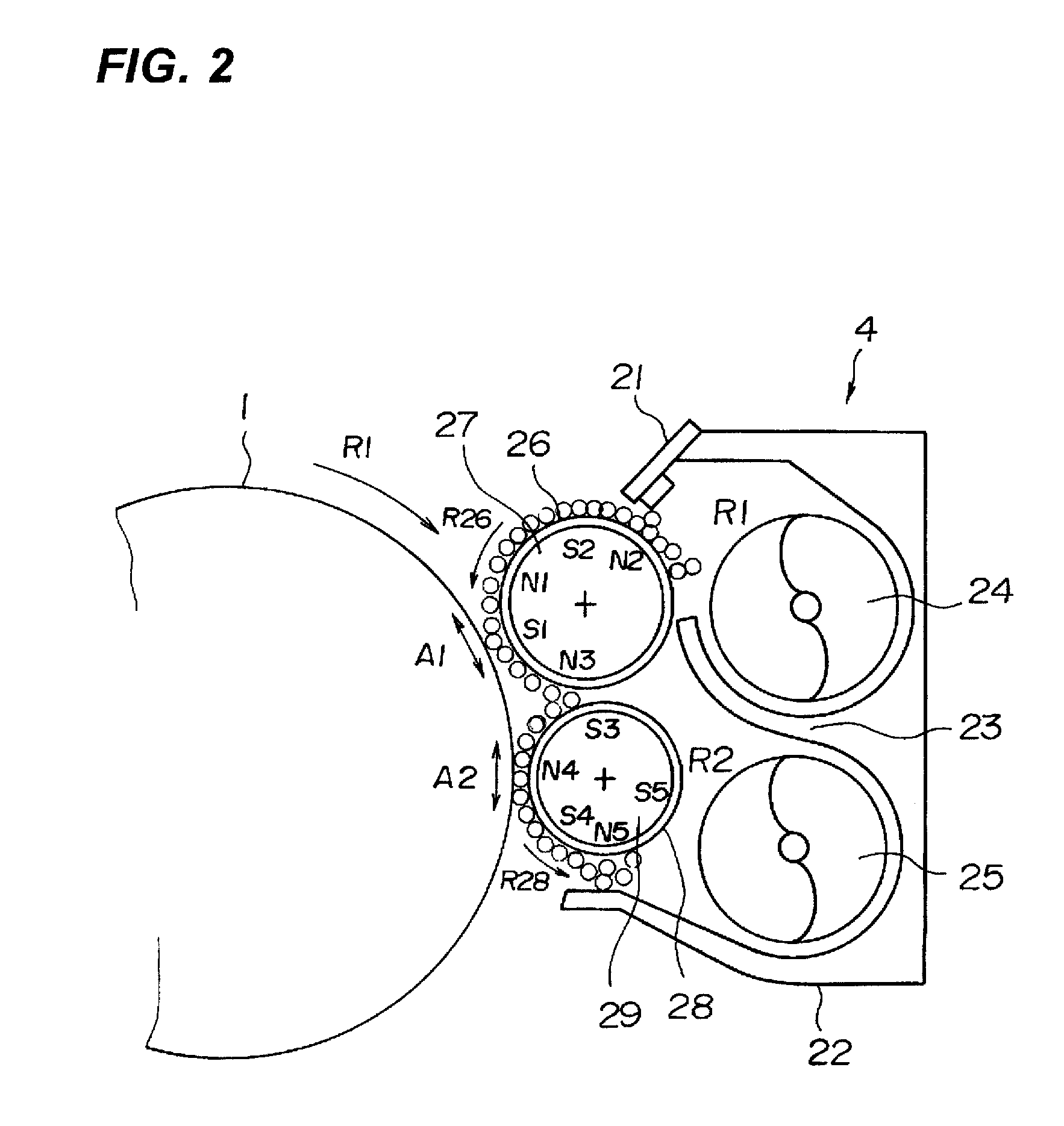
[0108]A second embodiment of the development apparatus of the present invention will be described next. FIG. 5 illustrates a structure of a development apparatus 4 of the embodiment. The same portions as those of the first embodiment are designated with the same symbols, and explanation thereof will be omitted.
[0109]As shown in FIG. 5, according to the development apparatus 4 of the second embodiment, in the development apparatus 4 of the first embodiment, an outer diameter of the second developing sleeve (developing sleeve 28) is smaller than that of the first developing sleeve (developing sleeve 26).
[0110]In view of wear resistance, the base material of the downstream developing sleeve 28 is stainless steel. Therefore, the downstream developing sleeve 28 is easily deformed by heat. However, since the downstream developing sleeve 28 does not have the restriction blade 21, the downstream developing sleeve 28 is not affected by thermal deformation, and there is no problem when it is ...
third embodiment
[0115]A third embodiment of the development apparatus of the present invention will be described next. FIG. 6 illustrates a structure of a development apparatus 4 of the embodiment. The same portions as those of the first and second embodiments are designated with the same symbols, and explanation thereof will be omitted.
[0116]Concerning the heat source which may cause the thermal deformation of the developing sleeve, a photosensitive drum 1 having a heater therein and a fixing apparatus can be conceived. As a countermeasure for this, it is conceived that the developing sleeve is separated away from the heat source as much as possible.
[0117]However, concerning the photosensitive drum 1 having a heater therein, if a distance between the photosensitive drum 1 and the developing sleeves 26 and 28 is too long, a problem that the developing performance is deteriorated occurs. Therefore, the distance can not exceed a certain level. The distance mentioned here is the shortest distance betw...
PUM
 Abstract
Description
Claims
Application Information
 - R&D
- Intellectual Property
- Life Sciences
- Materials
- Tech Scout
- Unparalleled Data Quality
- Higher Quality Content
- 60% Fewer Hallucinations
Browse by: Latest US Patents, China's latest patents, Technical Efficacy Thesaurus, Application Domain, Technology Topic, Popular Technical Reports.
© 2025 PatSnap. All rights reserved.Legal|Privacy policy|Modern Slavery Act Transparency Statement|Sitemap|About US| Contact US: help@patsnap.com