Eureka AIR delivers breakthrough ideas for toughest innovation challenges, trusted by R&D personnel around the world.

Low noise and energy saving air vacuum cleaner

a vacuum cleaner, low noise technology, applied in vacuum cleaners, cleaning equipment, electric equipment installation, etc., can solve the problems of waste of electricity, increased load, increased power of air pump drive motor, etc., to increase both noise level and power consumption, reduce power consumption, and reduce noise.

Inactive Publication Date: 2008-07-31
YANG TAI HER
View PDF4 Cites 19 Cited by
  • Summary
  • Abstract
  • Description
  • Claims
  • Application Information

AI Technical Summary

Benefits of technology

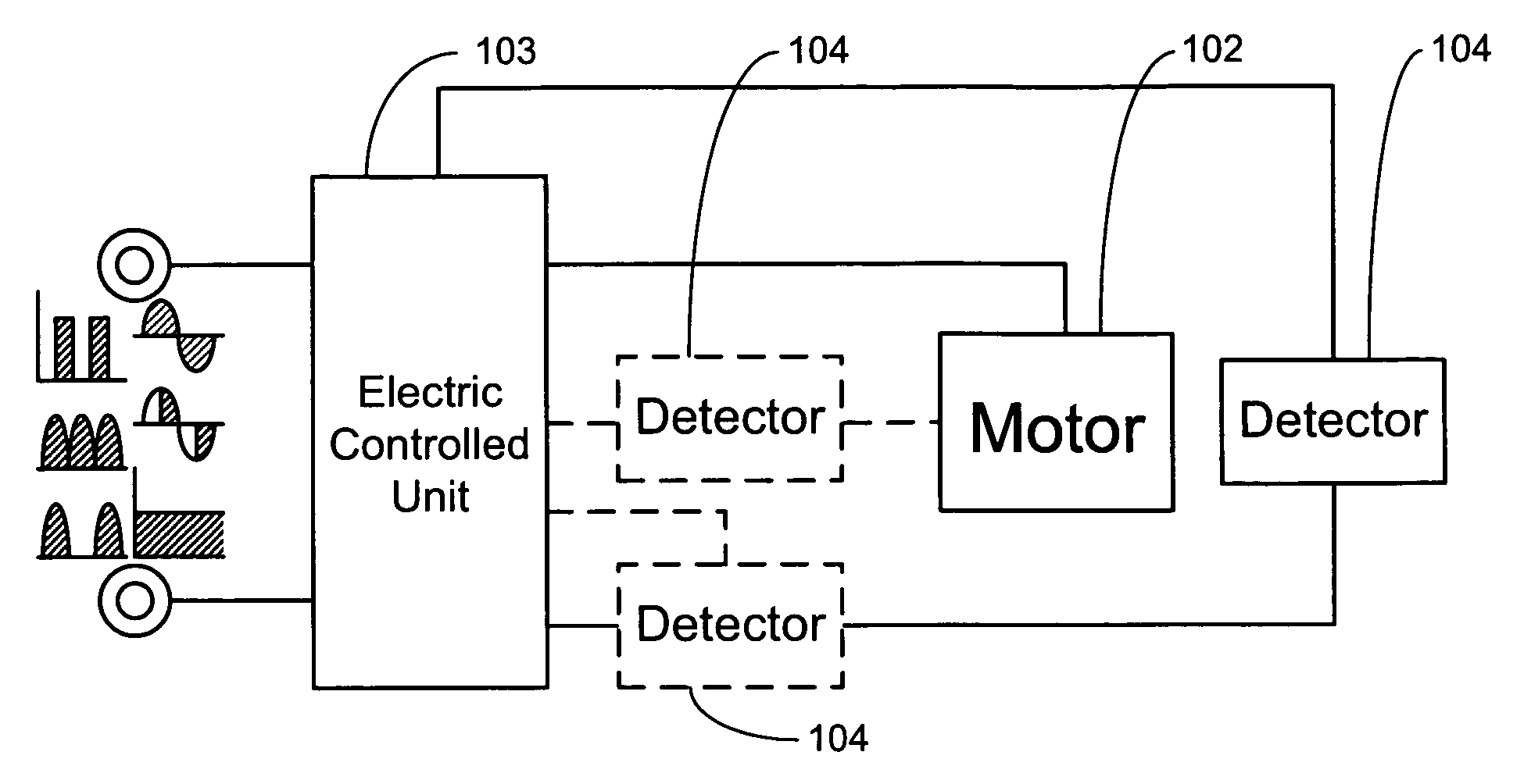
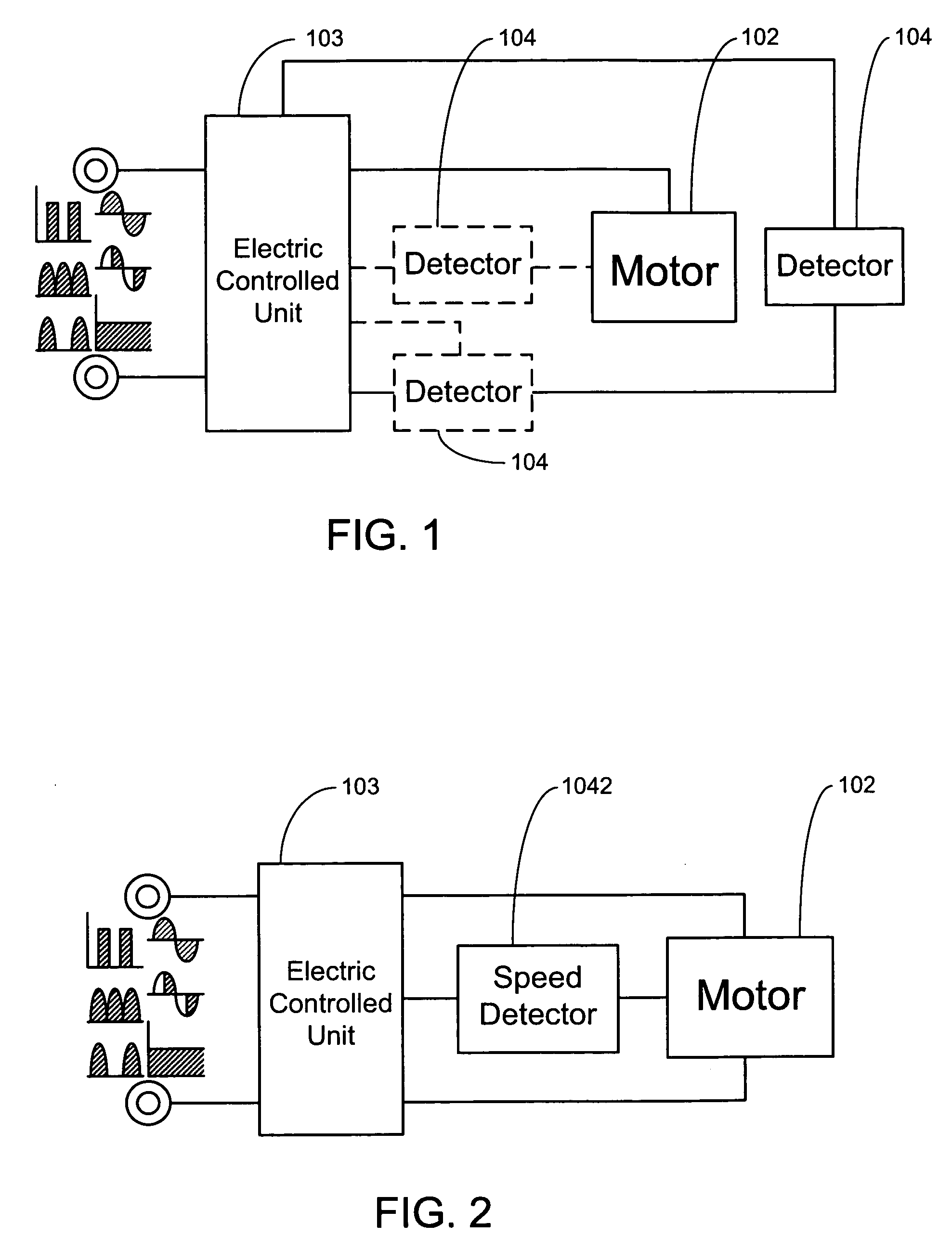
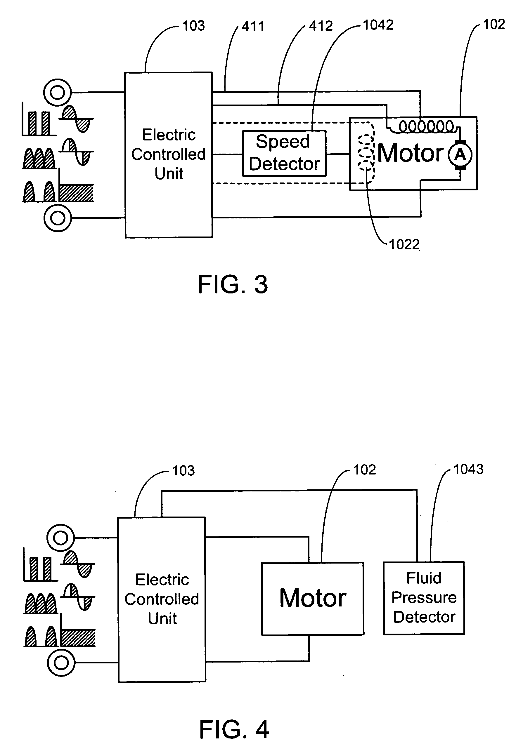
[0005]The primary purpose of the present invention is to provide a low noise and energy saving air vacuum cleaner by detecting the operation status of the cleaner to control the size of the electricity inputted to an air pump drive motor, or exercise the control of power delivery or power cut off. Accordingly, normal rated voltage is inputted when the cleaner is in normal working status; or the power outputted to the air pump drive motor is reduced or cut off when the cleaning tool of the cleaner clears away from its work area to render the cleaner in full load operation status as were a blower to increase both noise level and power consumption, or the cleaning tool is blocked due to excessive packing against the work area for achieving low noise level and energy saving purposes.

Problems solved by technology

The conventional air vacuum cleaner usually idles when the cleaning tool of the cleaner stays away from its work area, that is, the cleaner turns into a full load operation status as it were a blower to result in increased load and the power of the electricity outputted to an air pump drive motor is also increased to produce higher noise level and waste electricity, and to fail in providing vacuuming function and waste of electric energy when the cleaning tool is blocked due to excessive packing against the work area.

Method used


Image

  • Low noise and energy saving air vacuum cleaner
  • Low noise and energy saving air vacuum cleaner
  • Low noise and energy saving air vacuum cleaner

Examples


Embodiment Construction

[0019]A low noise and energy saving air vacuum cleaner that is capable of adjusting and controlling electric energy of the present invention may rely upon AC city power, or DC power, or a source unit of rechargeable batter for its input source. The present invention while being provided with the power cord, rechargeable battery source unit, operation switch, and fluid pump for vacuum cleaning, dust collection bag and other mechanism, casing and associate units and equipment related to the vacuuming operation is adapted with an electric controlled unit corresponding to the operation status of the air vacuum cleaner. The fashions of interacting control between the electric controlled unit and the source end include:

[0020](1) Active electric controlled unit: an electric controlled unit is comprised of having an impedance unit is connected in series with a power source and an air pump drive motor for executing active control of the power transported to the air pump drive motor of the ai...


PUM


Abstract

A low noise and energy saving air vacuum cleaner by detecting the operation status of the cleaner to control the size of the electricity inputted to an air pump drive motor, or exercise the control of power delivery or power cut off; normal rated voltage being inputted when the cleaner is in normal working status; or the power outputted to the air pump drive motor being reduced or cut off when the cleaning tool of the cleaner clears away from its work area to render the cleaner in full load operation status as were a blower to increase both noise level and power consumption, or when the cleaning tool is blocked due to excessive packing against the work area for reduced noise level and energy saving.

Description

BACKGROUND OF THE INVENTION[0001](a) Field of the Invention[0002]The present invention is related to an air vacuum cleaner, and more particularly to a low noise and energy saving air vacuum cleaner that is capable of adjusting and controlling electric energy depending on the load, having disposed an electric controlled unit between input source and air pump drive motor of the cleaner to input normal rated voltage when the cleaner is in normal working status; and to either reduce the power outputted to the air pump drive motor or cut off the power source to reduce noise level and save energy when the cleaning tool clears away from the its work area during off-load status, or when the cleaning tool is blocked due to excessive packing against the work area.[0003](b) Description of the Prior Art[0004]The conventional air vacuum cleaner usually idles when the cleaning tool of the cleaner stays away from its work area, that is, the cleaner turns into a full load operation status as it wer...

Claims


Application Information

Patent Timeline
Patent Type & Authority Applications(United States)
IPC IPC(8): H02P7/00A47L9/28
CPCA47L9/2805A47L9/2831Y02B40/82A47L9/2878A47L9/2842Y02B40/00
Inventor YANG, TAI-HER
Owner YANG TAI HER
Why Eureka
Eureka Blog
Learn More