
Image-forming system, image-forming apparatus, computer program, and image-forming method

Active Publication Date: 2008-07-24
BROTHER KOGYO KK
View PDF5 Cites 7 Cited by
  • Summary
  • Abstract
  • Description
  • Claims
  • Application Information

AI Technical Summary

Benefits of technology

[0015]Accordingly, since the judgment of whether or not the printing is to be carried out with the identifiable ink is made based on attribute information (the first information) of the identifiable ink filled in the ink cartridge (ink cartridge for identifying) installed in the cartridge installing section, and printing-person specifying information (the second information) of the printing person, it is possible to prevent unauthorized printing which is carried out by using the identifiable ink. Consequently, it is possible to specify assuredly the printing person of a printed matter based on the identifiable ink adhered to the printed matter.
[0052]In this case, since it is possible to select as to whether or not the printing is to be carried out by jetting the identifiable ink even when the ink cartridge having the identifiable ink filled has not been installed, it is possible to carry out printing in which an identifiable ink such as the DNA ink is used, only when necessary, and to suppress a wasteful consumption of the identifiable ink. Moreover, when the same printing person carries out continuously (in succession) the printing in which the identifiable ink is used and the printing in which only the image-forming ink is used, it is not necessary to remove and insert every time the ink cartridge filled with the identifiable ink.

Problems solved by technology

Therefore, even when the DNA ink is adhered to the recorded material, it is not possible to specify a person assuredly who has performed printing on the recorded material.

Method used


Image

  • Image-forming system, image-forming apparatus, computer program, and image-forming method
  • Image-forming system, image-forming apparatus, computer program, and image-forming method
  • Image-forming system, image-forming apparatus, computer program, and image-forming method

Examples


second modified embodiment

[0150]In a second modified embodiment, in addition to the serial number and the pattern data of DNA, information indicating whether or not that DNA ink cartridge 42 is a disabled cartridge of which the use has been inhibited (disable information) is recorded in the IC tag 42a of the DNA ink cartridge 42. Moreover, as shown in FIGS. 8A and 8B, the printer 3 further includes an IC tag writer 51 (information updating mechanism) which rewrites data in the IC tag 42a.

[0151]In the second modified embodiment, as shown in FIGS. 9A and 9B, instead of steps S105 and step S201 in the embodiment (refer to FIGS. 6A and 6B), the disable information recorded in the IC tag 42a is rewritten to information which indicates that the use of the DNA ink cartridge 42 has been inhibited (step S301). Moreover, instead of step S106 in the embodiment (refer to FIG. 6A), the pattern data of DNA and the disable information are read by the IC tag reader 17 from the IC tag 42a (step S302). Furthermore, instead o...

third modified embodiment

[0153]In a third modified embodiment, as shown in FIGS. 10A and 10B, the printer 3 further includes a DNA ink analyzing section 61 which analyzes the DNA ink in a DNA ink cartridge 42. Here, the DNA ink analyzing section 61 collects the DNA ink which is jetted from the DNA ink head 16 for example, or collects the DNA ink which is discharged from the DNA ink head 16 by carrying out a purge, and analyzes the ink which has been collected.

[0154]In the third modified embodiment, as shown in FIGS. 11A and 11b, without carrying out processes at steps from S104 to S106, and step S201 (refer to FIGS. 6A and 6B), when the DNA ink cartridge 42 is installed in the cartridge installing section 16a (YES at step S103), the DNA ink is analyzed by the DNA ink analyzing section 61 and the pattern data of the DNA is acquired (step S501), and thereafter, the process advances to step S107 similar as in the embodiment. Moreover, after step S107, without carrying out the processes at step S202 and S203 in...

fourth modified embodiment

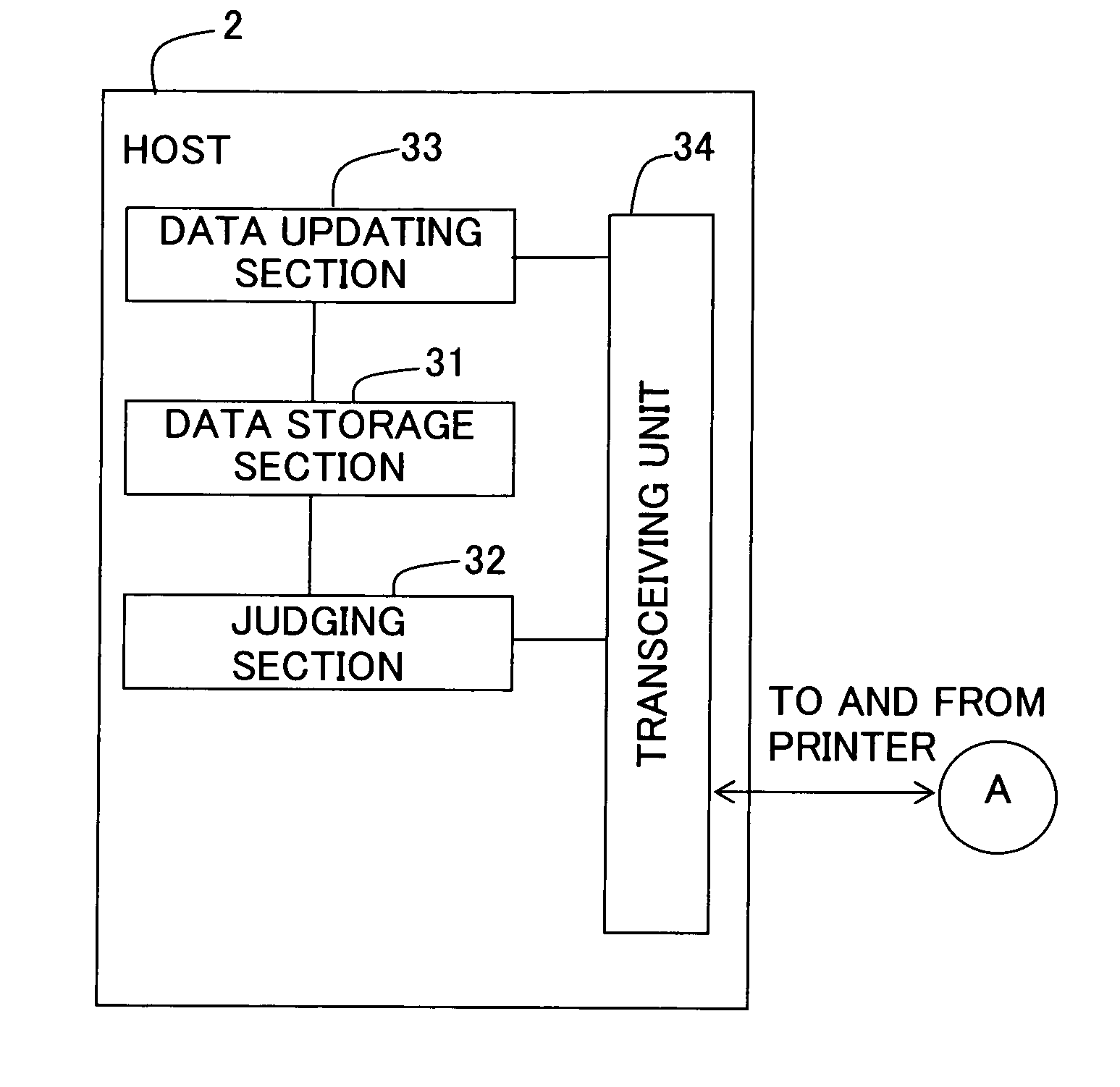
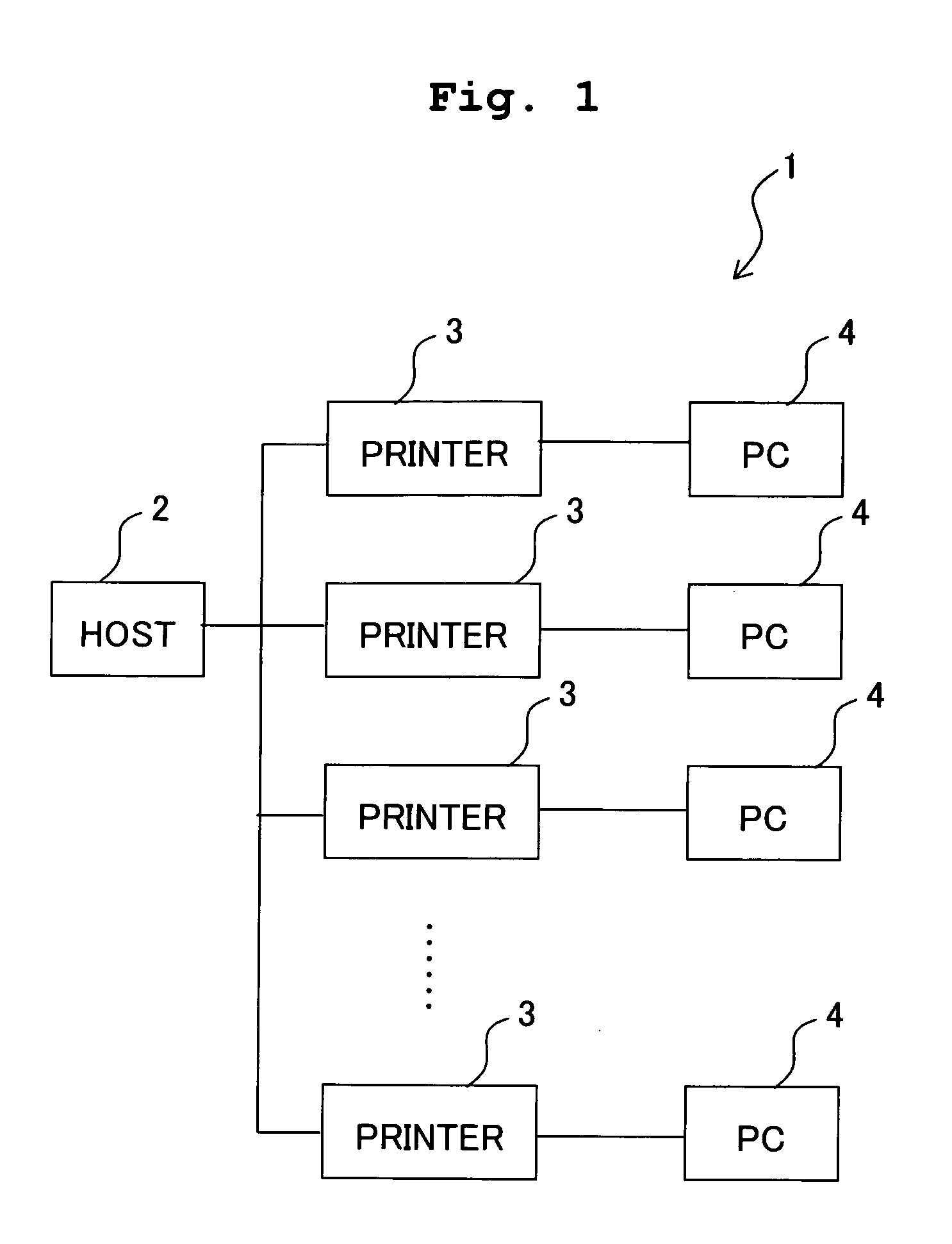
[0156]In the embodiment, the host 2 has the data storage section 31, the judging section 32, and the data updating section 33. However, without restricting to such structure, the printer may have a part of these functions. For example, in a fourth modified embodiment, as shown in FIGS. 12A and 12B, the control unit 19 of the printer 3 has a data storage section 71, a data updating section 72, and a judging section 73 in addition to the installation judging section 21, the ink-shortage judging section 22, the printing instruction section 23, the printing mode selecting section 24, and the driver IC 25 similar as in the embodiment. On the other hand, the host 2 has a data storage section 81, a judging section 82, and a data updating section 83.

[0157]Serial numbers and end flags corresponding to the serial numbers are stored upon associating in the data storage section 71. In other words, the data storage section 71 corresponds to a second memory of the present invention. When a judgme...


PUM


Abstract

When a DNA ink printing mode is selected, a serial number and a pattern data of DNA is read from an IC tag of a DNA ink cartridge and a fingerprint of a printing person is read by a fingerprint authenticating unit. The pattern of the fingerprint and DNA which have been read are verified with the pattern data of fingerprints and DNA in a memory and personal authentication is carried out. Thereafter, a DNA ink is jetted on to a recording paper, and printing of an image by an image forming ink is carried out. By carrying out printing by such a method, it is possible to specify the printing person who has created the printed matter.

Description

CROSS-REFERENCE TO RELATED APPLICATION[0001]The present application claims priority from Japanese Patent Application No. 2006-355668, filed on Dec. 28, 2006, the disclosure of which is incorporated herein by reference in its entirety.BACKGROUND OF THE INVENTION[0002]1. Field of the Invention[0003]The present invention relates to an image forming system and an image forming apparatus which record an image on a recording medium, a computer program which operates the image forming system and the image forming apparatus, and an image forming method.[0004]2. Description of the Related Art[0005]In image forming apparatuses which record an image on a recording medium such as a recording paper, there are apparatuses which make adhere an identifiable ink such as an ink containing DNA to the recording medium. For example, in an image forming apparatus described in Japanese Patent Application Laid-open No. 2002-72795, an image is printed on a paper by adhering a developer to the paper, and the...

Claims


Application Information

Patent Timeline
IPC IPC(8): B41J2/195
CPCB41J2/17546B41J2/17566C09D11/04C09D11/30G06Q30/0212G06F21/32G06F21/608G06Q20/085C09D11/38
Inventor SUGAHARA, HIROTOYAZAWA, HIROAKINISHIZAKI, MASAHIROMOMOZAKI, MOTOHIRO
Owner BROTHER KOGYO KK
Learn More