Method of adjusting the resonance frequency of an l-c resonant circuit and resonant circuit

a resonant circuit and resonance frequency technology, applied in the field of lc resonant circuits, can solve the problems of power consumption, problems such as the general limited tuning range of monolithic implemented resonator-based circuits (e.g. l-c oscillators, filters), and the difficulty in tuning integrated l-c circuits in such a way more sever

Active Publication Date: 2008-07-24
STMICROELECTRONICS SRL
View PDF1 Cites 46 Cited by
  • Summary
  • Abstract
  • Description
  • Claims
  • Application Information

AI Technical Summary

Benefits of technology

[0012]More precisely, this invention may provide a method of adjusting the resonance frequency of an L-C resonant circuit and an L-C resonant circuit with adjustable resonance frequency, comprising a capacitor and a first inductor connected electrically in parallel or in series, a second inductor magnetically coupled with t

Problems solved by technology

The main limitation of monolithic implemented resonator-based circuits (e.g. L-C oscillators, filters) is a generally limited tuning range.
This restriction results from design trade-offs between tuning range, noise, phase accuracy (if quadrature is required) and power consumption.
Process scaling toward the nanometer scale and the low supply voltage sources of portable applications like wireless devices, makes the problems in using integrated L-C circuits tuned in such a way more severe.
However, this approach is rarely followed because of the finite resistance of the selection switch when conducting worsens the quality factor figure of the resonant circuit.

Method used


Image

  • Method of adjusting the resonance frequency of an l-c resonant circuit and resonant circuit
  • Method of adjusting the resonance frequency of an l-c resonant circuit and resonant circuit
  • Method of adjusting the resonance frequency of an l-c resonant circuit and resonant circuit

Examples


Embodiment Construction

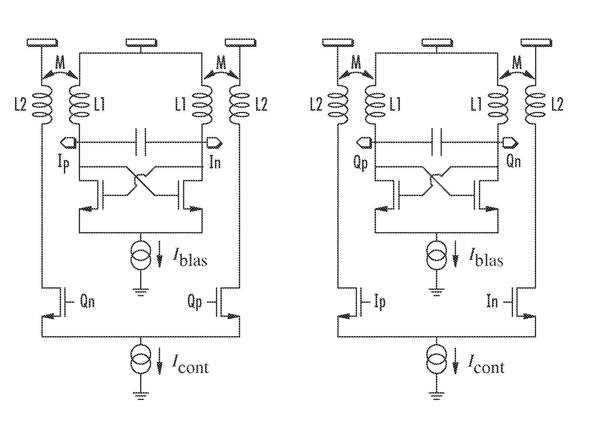
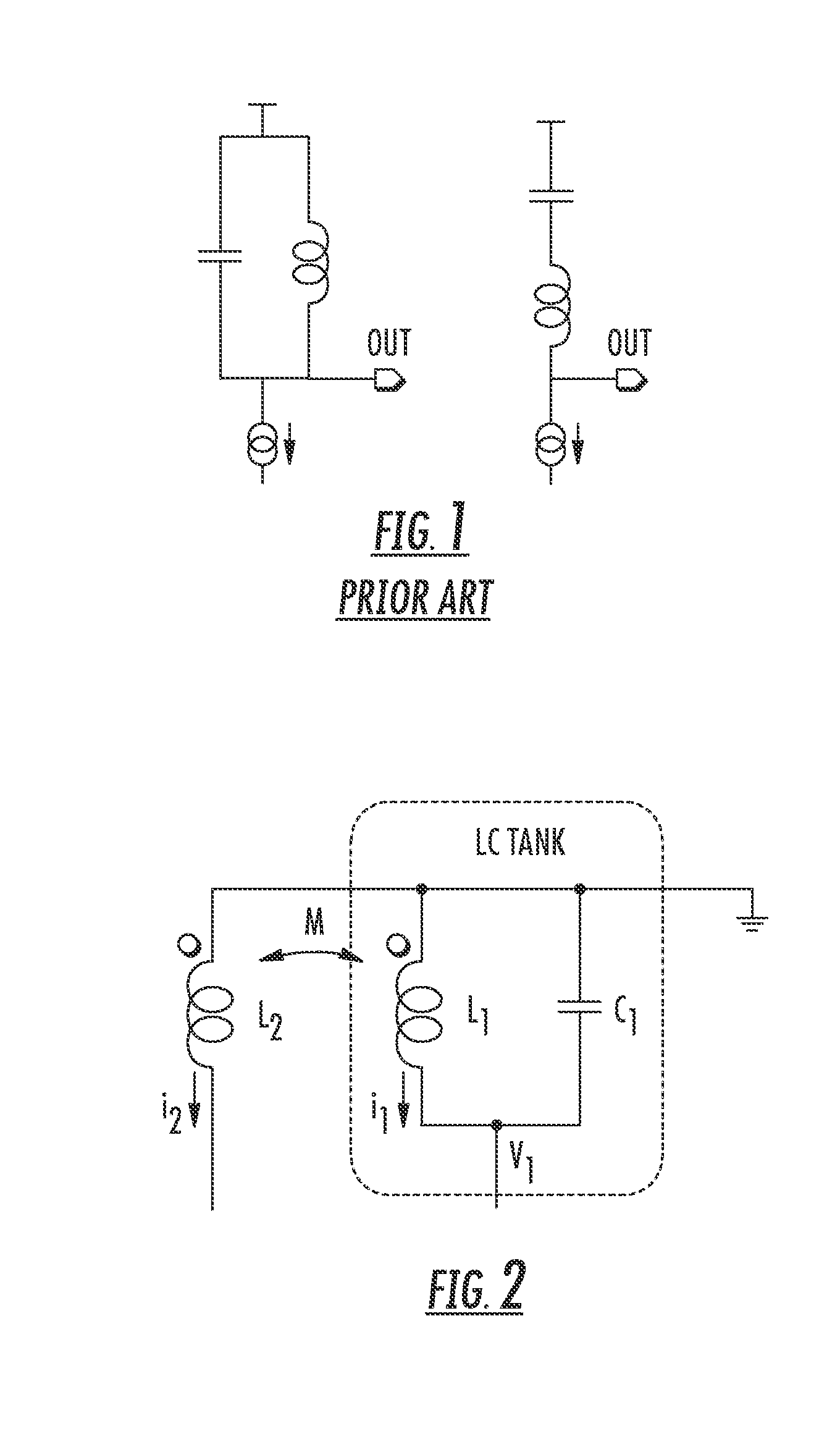
[0020]FIG. 2 shows the principle of the transformer-based L-C tank (or LMC tank). The innovative technique presented herein is based on the mutual magnetic coupling between the inductor L1 in the L-C tank and a second inductor L2. Preferably, the two inductors are the coils of a monolithically integrated transformer.

[0021]The resonance frequency of the L-C tank may be adjusted by controlling the AC current i2 flowing in the second inductor L2. By regulating the phase and / or the amplitude of the AC bias current forced through a primary winding it is possible to vary the resonance frequency of the L-C tank circuit.

[0022]Differently from known resonating circuits wherein transformers are commonly used only to achieve better phase noise figures, according to the method, a scaled and / or outphased replica current of the current flowing through the secondary winding L1 is forced through the primary winding L2 in order to vary the resonance frequency.

[0023]A mutual magnetic coupling M exist...


PUM


Abstract

An L-C resonant circuit with an adjustable resonance frequency, having a capacitor and a first inductor electrically coupled together and a second inductor magnetically coupled to the first inductor. Additionally, there is a control circuit to sense a signal representing a first current flowing through the first inductor and to force through the second inductor a second current that is a replica of the first current for setting the adjustable resonance frequency of the L-C resonant circuit.

Description

FIELD OF THE INVENTION[0001]This invention relates in general to L-C resonant circuits, and, more particularly, to an L-C resonant circuit with an adjustable resonance frequency and a method of adjusting the resonance frequency of an L-C resonant circuit.BACKGROUND OF THE INVENTION[0002]The demand for transmitters and receivers of greater and greater data rates is forcing manufacturers to realize devices capable of working at higher frequencies with a broad range of adjustment of the frequency. Typically, these devices include an L-C resonant circuit, such as that depicted in FIG. 1, that amplifies an input signal at a certain frequency.[0003]In order to fully exploit the advantages of working at a high frequency, it should be possible to tune these devices, i.e. to adjust the resonance frequency of the L-C resonant circuit. This may be done by including in the resonant circuit a plurality of inductors singularly connectable to the capacitor through selection switches, or by varying...

Claims


Application Information

Patent Timeline
IPC IPC(8): H03B5/08H03H7/00H03F3/66
CPCH03B27/00H03B5/1271H03F2200/336H03F2203/45296H03F2203/45318H03F2203/45704H03F2203/45731H03H7/0161H03H7/09H03H7/1775H03B5/1228H03B5/1296H03B5/1215H03B5/124H03F3/45188
Inventor CUSMAI, GIUSEPPEREPOSSI, MATTEOALBASINI, GUIDOSVELTO, FRANCESCO
Owner STMICROELECTRONICS SRL
Why Eureka
Try Eureka