
Lightweight Crane-Set Forming Panel

a technology of metal forming panels and cranes, which is applied in the direction of shaping building parts, forming/shuttering/falseworks, constructions, etc., can solve the problems of affecting the use of loose parts. , to achieve the effect of facilitating the us

Inactive Publication Date: 2008-07-24
WESTERN FORMS
View PDF10 Cites 58 Cited by
  • Summary
  • Abstract
  • Description
  • Claims
  • Application Information

AI Technical Summary

Benefits of technology

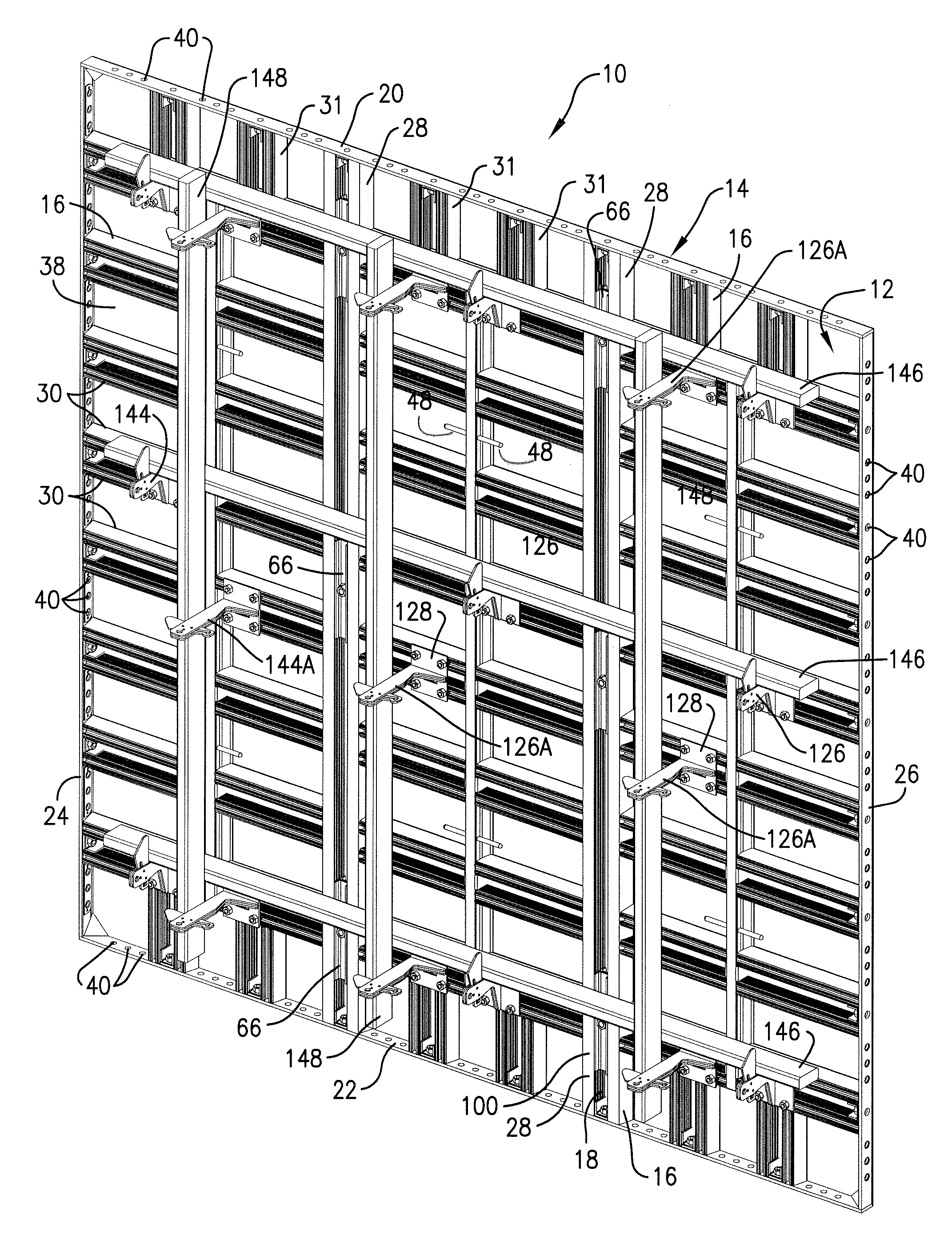
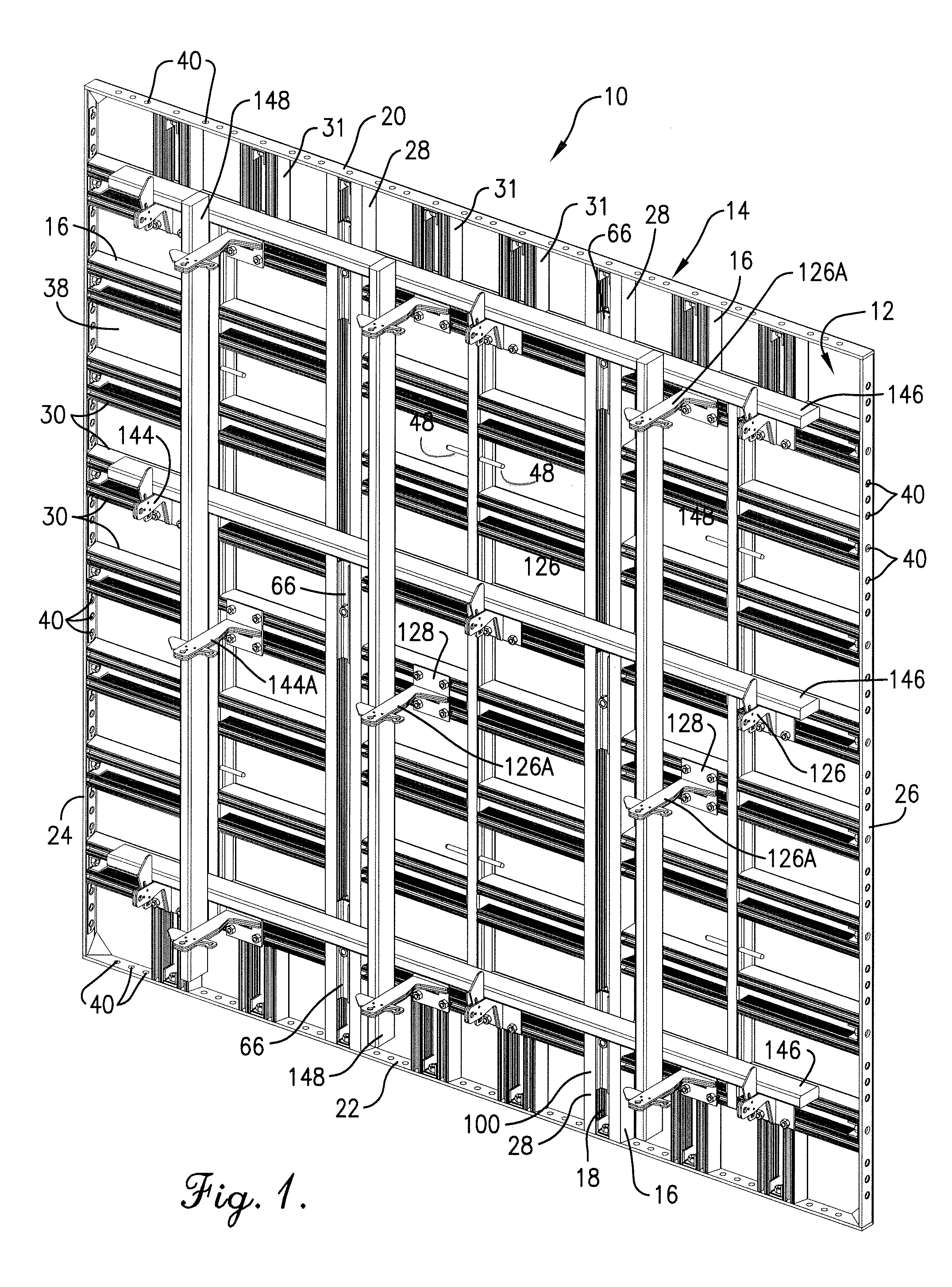
[0008]These and other objects have largely been addressed by the lightweight crane-set forming panel of the present invention. That is to say, the forming panel of the present invention presents significant improvements over prior art in regard to providing a lightweight panel of a size typical of crane-set forming panels, but presents improved capabilities for inhibiting the passage of fine particles of concrete around the frame or through openings in a face plate of the forming panel, and facilitates its use with other conventional panels by the provision of a folding bracket for holding a waler or other structural support. Moreover, while it is common to mount tie bars to the side rails of a forming panel, the present invention provides a forming panel capable of reuse and which permits the insertion of a tie rod or tie bar through an opening such as a hole or slot positioned internally of the side rails of the frame.
[0011]The channel, preferably though not necessarily unitary in construction and extending either fully or partially between the rails of the frame, and a central slot extending therealong is preferably threaded. As used herein in connection with the slot in the channel, the term “threaded” refers to the presence of opposed ridges or flights on the opposing, inward-facing sides of the wall surfaces of the channel forming the slot to permit a threaded member such as a bolt, stud, tie-rod or other externally threaded member to advance into and be withdrawn from the slot when rotated. Because the slot is open at the ends, an encircling opening with internal threads as typically understood by the term “threaded” is not provided, but the ridges on the channel nonetheless permit threadable attachment of such threaded members. Preferably, the channel includes at least a pair of wall surfaces each having a plurality of ribs which cooperatively define a threaded surface in the slot. The channel is preferably formed by extrusion whereby the threaded slot extends longitudinally along the channel permitting the positioning of a complementary threaded member, such as a bolt, receiver or plug, to be capable of infinite adjustment along the threaded portion of the channel. The threaded slot further preferably extends substantially the entire length of the channel. Multiple channels may be included in the frame in parallel or transverse orientations. For example, a first set of one or a plurality of channels may be oriented in an upright position when the panel is positioned for use, and another set of channels may be positioned in horizontal relationship. The channels not only serve to provide a grid for multiple attachment locations for accessories to the panel, but also help to reinforce the face panel against deflection. Both the face panel and the frame may be provided of aluminum alloy or other suitable metal which is durable and capable of outdoor use. The face plate may also be provided as a composite panel of layers of material such as synthetic resin and metal sheets. The channel may also have external serrations to facilitate gripping of the channel by clamps or other accessories. Beneficially, the preferred embodiment of the invention further includes slot rails accessible from the rear of the form which may be positioned laterally from but extend parallel to the channel. The slot rails may advantageously sized so as to capture and hold a nut or bolt head against turning, thereby greatly facilitating attachment and then tightening to the rear side of the form of form hardware such as the shiftable support bracket described above.
[0013]The forming panel hereof is useful as part of a forming system wherein a plurality of such panels may be connected by fasteners to provide a forming wall which faces another, opposite one of the forming walls to receive poured cementations material such as concrete therebetween. The threaded slots in the channels and the non-threaded slot rails of the channels greatly facilitate the attachment and securement of tie rods at multiple locations internal to the surrounding edges of the form and the mounting of hardware and accessories such as an expandable wall brace, a horizontal waler, a scaffold bracket, a lifting bracket with a clevis, and a gang leveler without the need for small nuts which must be positioned in narrow channel slots. Rather, the bolts for coupling such members to the panel may be secured directly to the panel and threaded into the channels while retaining the capability of infinite adjustment along the threaded portion of the panel. Moreover, the forming panel of the present invention may be provided of a reduced rearward depth from the face plate as compared to other crane set forms. This permits the forming panel of the present invention to favorably align along the rear side of the frame, so that the forming panel is complemental in depth and location of holes in the rails to smaller, typically man-set forms. Thus, while retaining the strength required of large, crane-set forms, the forming panel of the present invention can be placed side-by-side with smaller man-set forms and readily coupled thereto using pins and wedges or other fastening members such as the PINLOCK fastener of Western Forms as shown in U.S. Pat. No. 5,058,855, the entire disclosure of which is incorporated by reference. In addition, a waler or scaffold placed in spanning relationship across the crane-set form of the present invention may not only provide alignment of the forming panel hereof, but also smaller man-set forms.

Problems solved by technology

Such loose parts are problematic at a construction site, being broken, misplaced or lost as the forming walls are disassembled or moved.
Moreover, the location for receipt of these attachment members were limited and by necessity often were between reinforced areas of the forming panels and thus placed stress on portions of the panels in locations least configured to accept such stresses and strains.
However, the use of the “O” ring as a sealing member requires relatively frequent replacement and provides limited tolerances to differences in the diameters of the tie rod against which it seals.
Furthermore, the use of the “O” ring as a sealing member presents inherent limitations as to the dimensions or configuration of the tie rod, and typically not configured for sealing around conventional tie bars to inhibit the passage of concrete therepast.
While improvements in inhibiting leakage around a form and to an extent through openings in the form are shown in U.S. Pat. No. 6,655,650, the improvements in such sealing have been limited to use on the forming panel itself, and limited in the ability to provide a barrier to concrete intrusion when an opening is later made through the face plate of the forming panel inboard of the side rail or other parts of the frame.

Method used


Image

  • Lightweight Crane-Set Forming Panel
  • Lightweight Crane-Set Forming Panel
  • Lightweight Crane-Set Forming Panel

Examples


Embodiment Construction

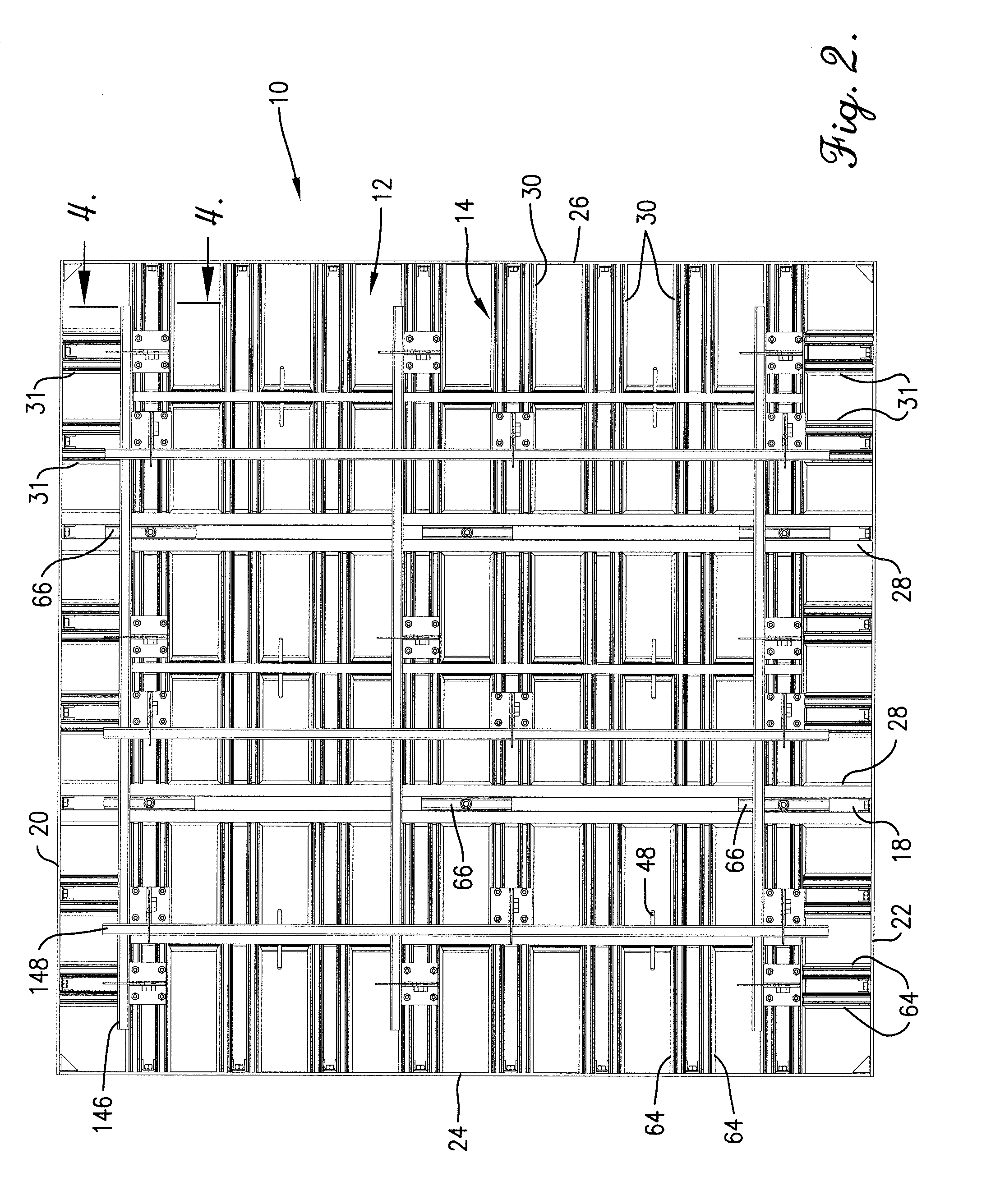
[0037]Referring now to the drawings, a forming panel 10 in accordance with the present invention broadly includes a face plate 12 and a frame 14 and includes at least one channel 16 having an elongated, internally threaded slot 18. The forming panel 10 is preferably of aluminum or an aluminum alloy. The frame 14 preferably includes upper rail 20, lower rail 22 and side rails 24 and 26. The face plate 12 is a generally planar sheet of aluminum or aluminum alloy welded to the frame 14. Alternatively, as shown in FIGS. 21 and 22, a face plate 12A may be of a composite structure mounted to the frame 14 and mechanically held by groove or other fasteners such as adhesive bonding. Preferably, a plurality of channels 16 are provided, such that at least one of the channels 16 and two of the rails are oriented to be generally parallel to one another, with other channels 16 oriented generally normal to the at least one of the channels 16. The channels 16 are preferably formed by extruding in a...


PUM


Abstract

A forming panel is provided which is particularly useful as a large, crane-set forming panel for forming concrete walls. The forming panel includes a face plate and a frame, the frame including channels having a slot extending longitudinally therealong. The slot is adapted to receive a filler insert having a bushing which includes a flexible barrier having a brush-like element with a plurality of filaments extending into a passage configured to receive either a tie bar or a tie rod. The forming panel preferably includes a shiftably mounted bracket for supporting a waler, scaffold or strongback thereon, wherein the bracket includes an arm which may be pivoted to a position substantially parallel to the frame and its mounting plate for transport and / or storage. The face plate may be provided as a multilayered composite panel and the frame may include rails having grooves on the side opposite the face plate which receive flexible barriers for inhibiting the passage of fine particles of concrete therepast.

Description

[0001]This application claims the benefit of U.S. Provisional Application No. 60 / 885,587, filed Jan. 18, 2007.BACKGROUND OF THE INVENTION[0002]1. Field of the Invention[0003]The present invention concerns a lightweight metal forming panel used in the construction of concrete or other cementations walls. More particularly, the present invention concerns a forming panel which is constructed with dimensions typical of a crane-set forming panel but lighter in weight, may include a composite face plate and a frame including a resilient barrier, and may feature a reinforcing spine adapted to receive a shiftable bracket which permits sealing against internally placed form connecting elements such as ties bars or tie rods of different configurations and includes a retractable support bracket.[0004]2. Description of the Prior Art[0005]Forming panels are well known in the construction industry as providing a system for retaining flowable cementatious material such as concrete in a desired sha...

Claims


Application Information

Patent Timeline
IPC IPC(8): E04G9/00E04G17/00
CPCE04G11/10E04G17/002E04G17/0652E04G17/047E04G17/045E04G17/007E04G2017/0646
Inventor BREWKA, ROMANWARD, RONALD A.
Owner WESTERN FORMS
Learn More