
Methods and Systems for Power Management in a Data Processing System

a data processing system and power management technology, applied in the field of data processing systems, can solve problems such as unreliable power management, and achieve the effect of reducing the latency of the power up process

Active Publication Date: 2008-07-10
APPLE INC
View PDF33 Cites 135 Cited by
  • Summary
  • Abstract
  • Description
  • Claims
  • Application Information

AI Technical Summary

Benefits of technology

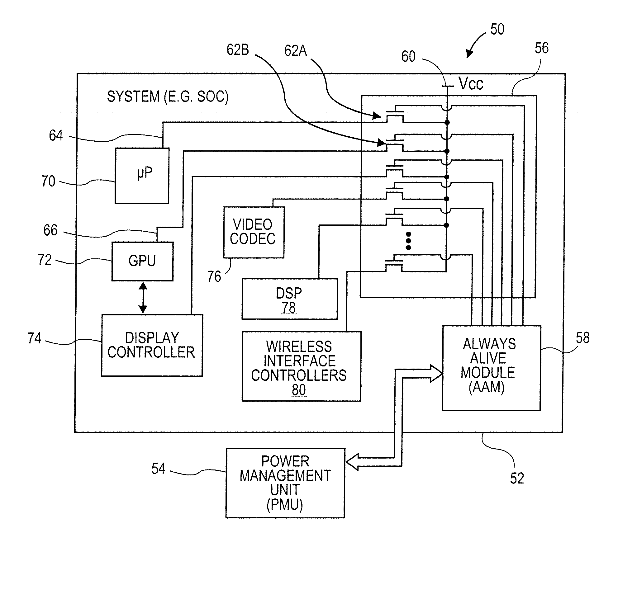
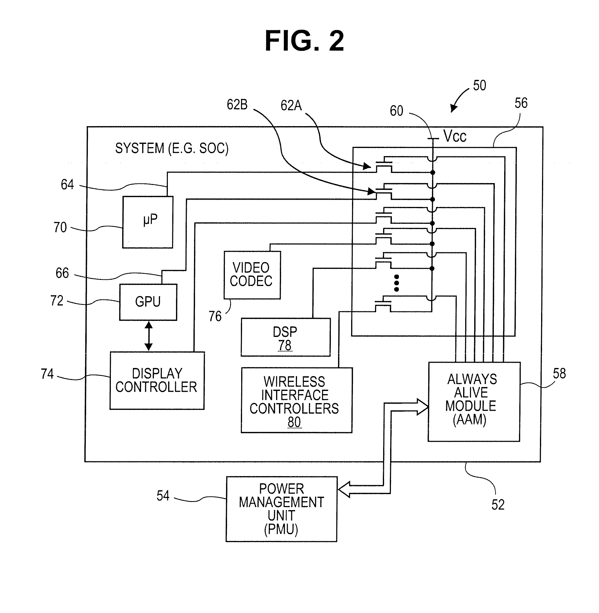
[0011]In one embodiment of the inventions, a data processing system includes a processing unit, at least one bus coupled to the processing unit, at least one subsystem coupled to the at least one bus, a memory coupled to the at least one bus, and a power controller coupled to the processing unit. The memory may be configured to store data representing a future action for at least one of the subsystems and the processing unit, and the future action is being scheduled for a future time adjusted with a latency value which represents a latency in powering, up at least one of the subsystem or the processing unit from a reduced power state. The power controller may be configured to supply power to the at least one of the subsystem or the processing unit in response to the future time as adjusted by the latency value. In one embodiment, this allows the data processing system to schedule a future event and cause a subsystem to be placed in a reduced power state and then retrieve that subsystem from the reduced power state at a slightly earlier time in order to reduce the latency of the power up process for the subsystem thereby making the system appear as if the subsystem had not been placed in a reduced power state. In other words, the system seems as responsive as a system which had not placed the subsystem in a reduced power state.

Problems solved by technology

This approach does not take into account the status of an instruction queue relative to a system which may be turned off before events which are scheduled in the instruction queue.

Method used


Image

  • Methods and Systems for Power Management in a Data Processing System
  • Methods and Systems for Power Management in a Data Processing System
  • Methods and Systems for Power Management in a Data Processing System

Examples


Embodiment Construction

[0030]Various embodiments and aspects of the inventions will be described with reference to details discussed below, and the accompanying drawings will illustrate the various embodiments. The following description and drawings are illustrative of the invention and are not to be construed as limiting the invention. Numerous specific details are described to provide a through understanding of various embodiments of the present invention. However, in certain instances, well-known or conventional details are not described in order to provide a concise discussion of embodiments of the present inventions.

[0031]The present invention can relate to an apparatus for performing one or more of the operations described herein. This apparatus may be specially constructed for the required purposes, or it may comprise a general purpose computer selectively activated or reconfigured by a computer program stored in the computer. Such a computer program may be stored in a machine (e.g. computer) reada...


PUM


Abstract

Methods and systems for managing power consumption in data processing systems are described. In one embodiment, a data processing system includes a general purpose processing unit, a graphics processing unit (GPU), at least one peripheral interface controller, at least one bus coupled to the general purpose processing unit, and a power controller coupled to at least the general purpose processing unit and the GPU. The power controller is configured to turn power off for the general purpose processing unit in response to a first state of an instruction queue of the general purpose processing unit and is configured to turn power off for the GPU in response to a second state of an instruction queue of the GPU. The first state and the second state represent an instruction queue having either no instructions or instructions for only future events or actions.

Description

BACKGROUND OF THE INVENTION[0001]At least certain aspects of the inventions relate to data processing systems and the management of power consumption on those systems. Other aspects of the inventions described herein relate to methods and systems for time keeping in a data processing system.[0002]Power management on a data processing system often involves techniques for reducing the consumption of power by components in the data processing system. The data processing system may be a laptop or otherwise portable computer, such as a handheld general purpose computer or a cellular telephone. The management of power consumption in a portable device which is powered by a battery is particularly important because better power management usually results in the ability to use the portable device for a longer period of time when it is powered by one or more batteries.[0003]Conventional systems typically utilize timers to indicate when a subsystem should be turned off after a period of inacti...

Claims


Application Information

Patent Timeline
Patent Type & Authority Applications(United States)
IPC IPC(8): G06F1/32
CPCG06F1/3203G06F1/3237G06F1/324Y02B60/1221Y02B60/1282G06F1/3287Y02D10/00
Inventor DE CESARE, JOSHUASEMERIA, BERNARDSMITH, MICHAEL
Owner APPLE INC
Learn More