
Drill bit assembly for bone tissue including depth limiting feature

a bone tissue and depth limitation technology, applied in the field of drill bit assembly, can solve the problems of limited clinician's ability to use these visual markers, the inability to properly perform sterilization process, and the root of adjacent teeth may be affected by the bore siz

Active Publication Date: 2008-07-10
BIOMET 3I LLC
View PDF31 Cites 70 Cited by
  • Summary
  • Abstract
  • Description
  • Claims
  • Application Information

AI Technical Summary

Benefits of technology

The patent describes a drill assembly for creating bores in living bone. The assembly includes a drill bit, collet-nose drill stop, collet sleeve, collet body, concealment collar, retaining spring, and retaining balls. The drill bit has flutes that create the bore, while the collet-nose drill stop has a connecting ledge, extending portion, receptacle portion, and anti-rotation portion. The collet sleeve has a protruding connection region, a first threaded region, and a plurality of retaining ball receiving holes. The collet body has a drive shank and a connection region with a receiving portion, a press-fit region, a shoulder, and a plurality of retaining ball receiving holes. The collet-nose drill stop and collet sleeve are designed to secure the drill bit and limit the depth of the bore. The retaining spring is positioned over the connection region and exerts a force on both the shoulder of the collet body and the collet sleeve. The retaining balls interact with the drill bit and collet body to secure the drill bit. The assembly provides a simple and effective way to create bores in living bone.

Problems solved by technology

Likewise, the roots of adjacent teeth also may be affected by the size of the bore.
The use of these visual markers is, of course, limited to the clinician's ability to see the mark as the drill is being inserted into the patient's mouth.
However, a sterilization process may not always be properly performed, resulting in the introduction of bacteria and other pathogens to a patient.
Additionally, some sterilization processes may damage certain features on a drill bit.

Method used


Image

  • Drill bit assembly for bone tissue including depth limiting feature
  • Drill bit assembly for bone tissue including depth limiting feature
  • Drill bit assembly for bone tissue including depth limiting feature

Examples


Embodiment Construction

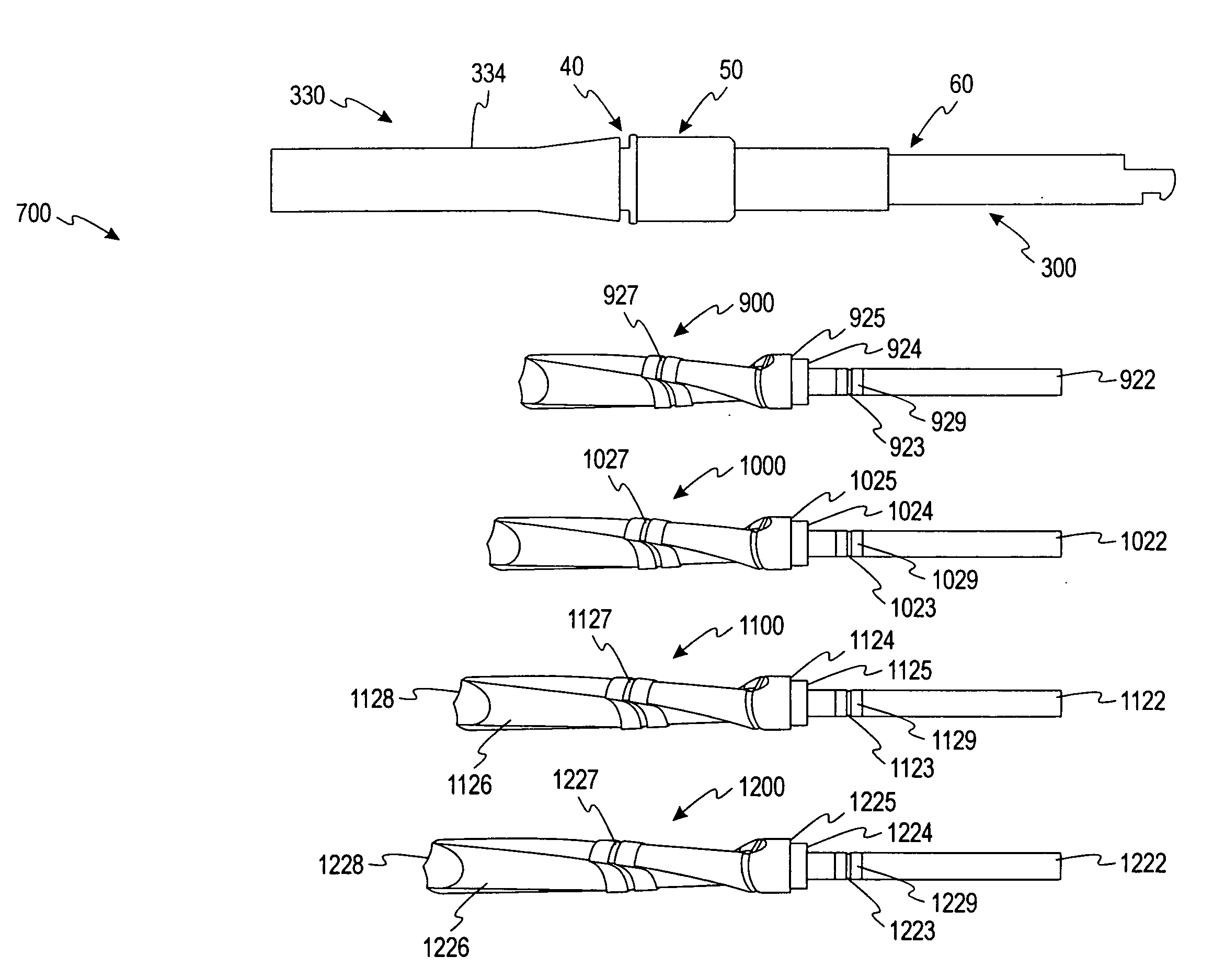
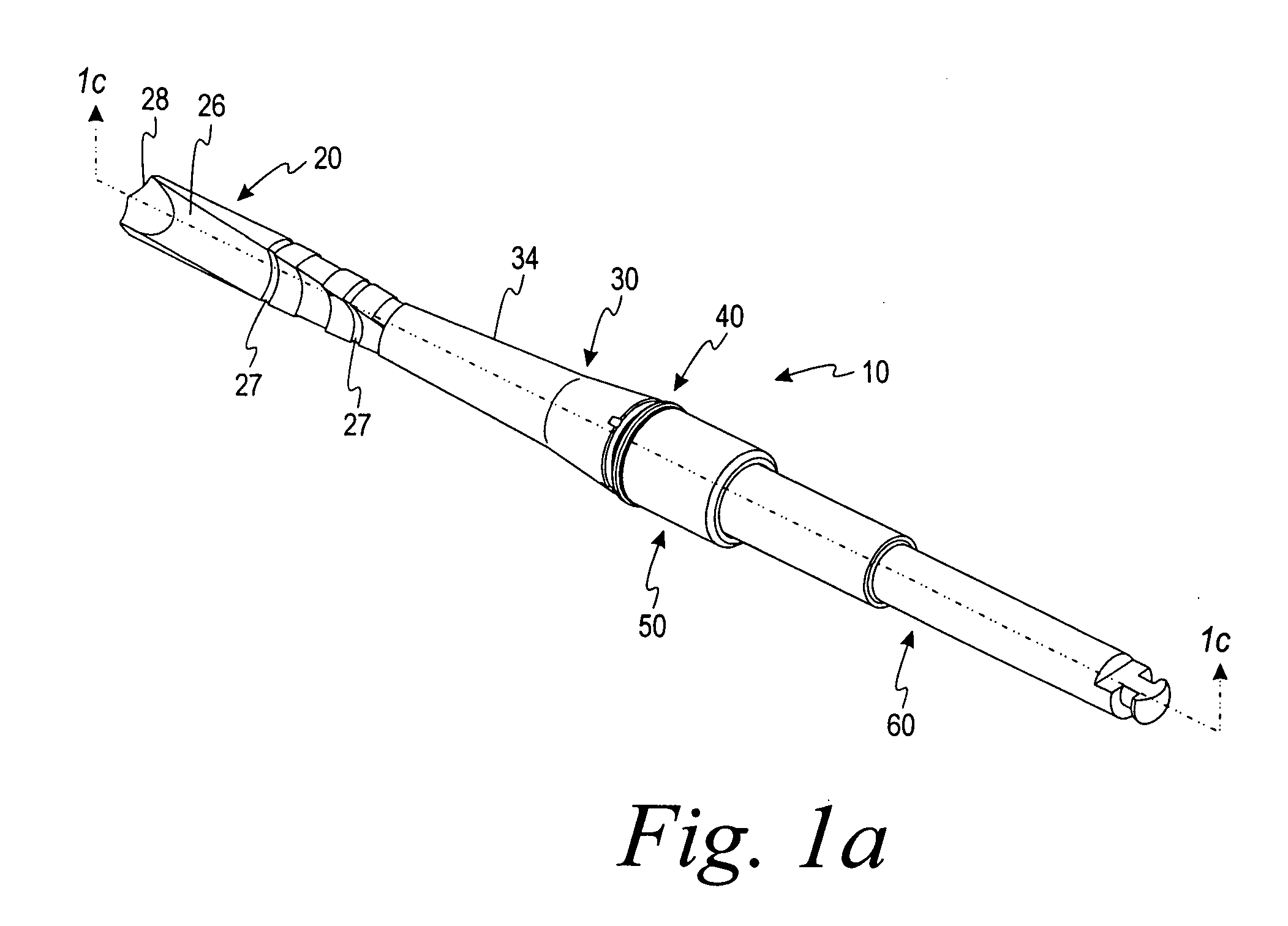
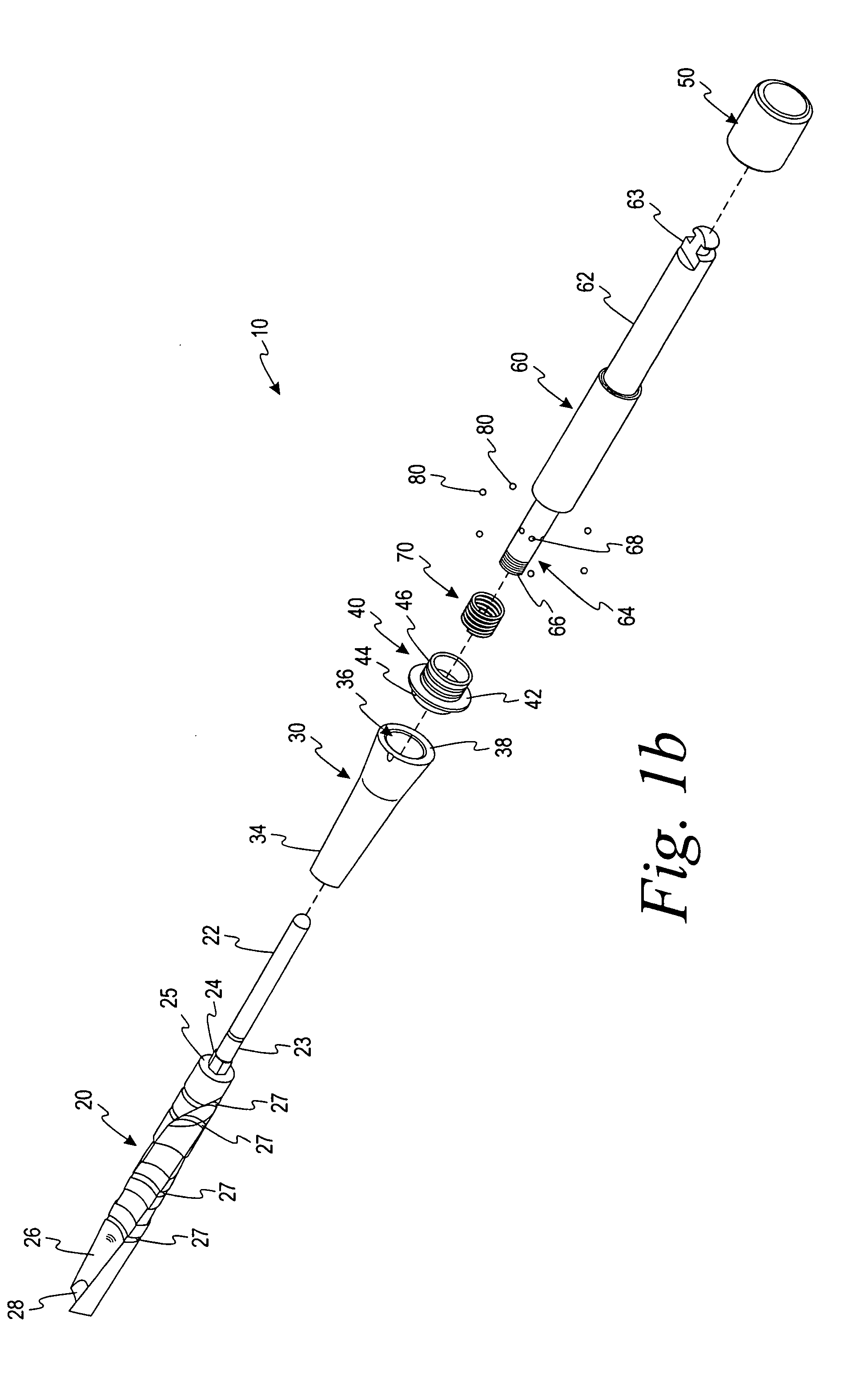
[0024]As shown in FIGS. 1a-1c, a drill assembly 10 comprises a drill bit 20, a collet nose drill stop 30, a collet sleeve 40, a concealment collar 50, a collet body 60, a retaining spring 70, and a plurality of retaining balls 80. The various components of the drill assembly 10 are each described in greater detail below.

[0025]The drill bit 20 includes a drive portion 22 at its one end that inserts into a receiving portion 65 (FIG. 2a) of the collet body 60. The drive portion 22 further has a retaining groove 23 around a periphery of the drive portion 22. The retaining groove 23 receives the plurality of retaining balls 80 to secure the drill bit 20 within the drill assembly 10. An anti-rotational portion 24 is located at a shoulder 25. The anti-rotational portion 24 shown in FIGS. 1a-1c has a hexagonal shape, but any other non-round cross sectional shape may be utilized. Each of a plurality of flutes 26 terminates in a cutting edge 28 which slices the bone tissue to develop a bore. ...


PUM


Abstract

A drill assembly for creating a bore in living bone comprises a drill bit, a collet-nose drill stop, a collet sleeve, a collet body, a concealment collar, a retaining spring, and a plurality of retaining balls. The drill bit inserts into the collet body and is retained in the collet body by the plurality of retaining balls. The collet-nose drill stop extends over a portion of the drill bit to limit the depth of the bore formed by the drill bit. The collet body has a drive shank and a connection region. The connection region of the collet body is adapted to receive a portion of the drill bit. The plurality of retaining balls are adapted to longitudinally secure the drill bit to the collet body.

Description

CROSS REFERENCE TO RELATED APPLICATIONS[0001]This application claims the benefit of the U.S. Provisional Application 60 / 878,764, filed on Jan. 5, 2007, which is hereby incorporated by reference in its entirety.FIELD OF INVENTION[0002]The invention relates to devices for developing a bore in bone tissue and, in particular, to a drill bit assembly that prohibits insertion of that assembly into the bone tissue beyond a predetermined depth.BACKGROUND OF THE INVENTION[0003]It is common for a dentist, or oral surgeon, to use tools such as drills, to create bores in bone tissue of a patient's mouth. Drills come in various styles, sizes, and lengths, but all have a common goal of creating a bore of a known size. The diameter of the drill dictates the diameter of the bore. However, the length of the bore is determined by the amount of axial movement that the clinician imparts on the drill as he or she inserts the drill into the bone tissue.[0004]The size of the bore is a critical parameter i...

Claims


Application Information

Patent Timeline
Patent Type & Authority Applications(United States)
IPC IPC(8): A61B17/56
CPCA61B17/1615A61B17/162A61B17/1633A61B17/1673A61C8/0089A61B2017/0023A61B2017/00464A61B2019/306A61B2019/462A61B17/1688A61B2090/036A61B2090/062
Inventor WATLINGTON, MICHAEL B.ROBB, T. TAIT
Owner BIOMET 3I LLC
Learn More