
Method for limiting service, method for limiting image processing and image processing system

Active Publication Date: 2008-07-03
KONICA MINOLTA BUSINESS TECH INC
View PDF7 Cites 13 Cited by
  • Summary
  • Abstract
  • Description
  • Claims
  • Application Information

AI Technical Summary

Benefits of technology

[0020]The structure described above makes it possible to place limitations on the use of a service provided by an image forming apparatus for a client such as a personal computer more reliably than ever before.

Problems solved by technology

Some of these functions, for example, the color printing function, are expensive compared to conventional cases.
If the decision whether these functions are used is completely left to a user of each personal computer, then a possibility may arise that the cost is increased.

Method used


Image

  • Method for limiting service, method for limiting image processing and image processing system
  • Method for limiting service, method for limiting image processing and image processing system
  • Method for limiting service, method for limiting image processing and image processing system

Examples


first embodiment

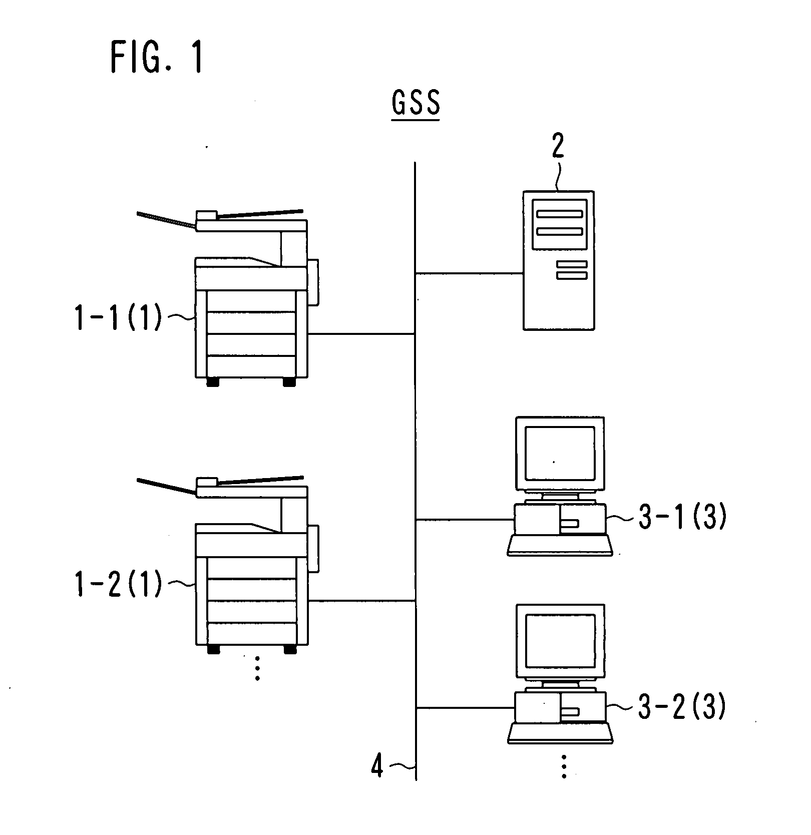
[0048]As shown in FIG. 1, an image processing system GSS according to an embodiment of the present invention includes a plurality of image forming apparatuses 1-1, 1-2, a driver management apparatus 2, a plurality of information processing apparatuses 3-1, 3-2, . . . and a communication line 4. Hereinafter, the image forming apparatuses 1-1, 1-2, . . . are collectively referred to as “image forming apparatuses 1”. Likewise, the information processing apparatuses 3-1, 3-2, . . . are collectively referred to as “information processing apparatuses 3”.

[0049]Each of the image forming apparatuses 1, the driver management apparatus 2 and each of the information processing apparatuses 3 can be interconnected via the communication line 4. The communication line 4 can be a LAN line, a wireless communication line, a public line, a dedicated line or the Internet.

[0050]The image processing system GSS is established in an organization such as a company or a public office and is used by a person b...

second embodiment

[0169]In the first embodiment, the information processing apparatus 3 encrypts print data DT0 and sends the encrypted print data DT0 to the image forming apparatus 1. The image forming apparatus 1 performs a printing process in the case where the print data DT0 could be decoded normally. Stated differently, the image forming apparatus 1 determines the validity of the print request source by the decoding result of the print data DT0.

[0170]In the second embodiment, an identifier (ID) issued on an information processing apparatus 3 basis is used to determine the validity of the print request source.

[0171]The entire configuration of the image processing system GSS according to the second embodiment is the same as that of the first embodiment and is as shown in FIG. 1. The hardware configuration of each of the image forming apparatus 1, the driver management apparatus 2 and the information processing apparatus 3 is the same as those in the first embodiment.

[0172]In the second embodiment,...


PUM


Abstract

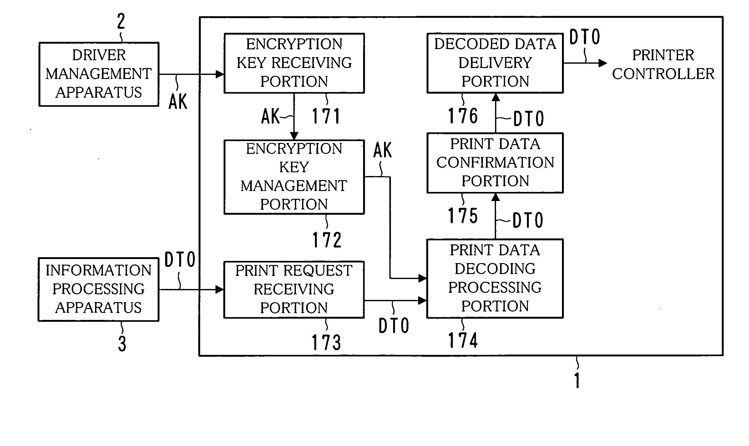
A driver management apparatus is installed in a system including an image forming apparatus and plural information processing apparatuses. The driver management apparatus sends the information processing apparatus a driver for the image forming apparatus with a first key incorporated. The driver is so set that printing processing conditions whose designation with the information processing apparatus is prohibited cannot be designated. Further, the driver management apparatus sends the first key to the image forming apparatus. The information processing apparatus uses the driver sent by the driver management apparatus to generate print data and encrypts the generated print data using the first key incorporated into the driver, and sends the encrypted print data to the image forming apparatus. The image forming apparatus decodes the print data received from the information processing apparatus using a second key of the information processing apparatus and performs a printing process using the decoded print data.

Description

[0001]This application is based on Japanese patent application No. 2006-352276 filed on Dec. 27, 2006, the contents of which are hereby incorporated by reference.BACKGROUND OF THE INVENTION[0002]1. Field of the Invention[0003]The present invention relates to a method for limiting the use of an image forming apparatus such as an MFP, and a system including the image forming apparatus.[0004]2. Description of the Related Art[0005]Image forming apparatuses called Multi Function Peripherals (MFPs) are prevalent in offices and others. Such image forming apparatuses have various functions including a copy function, a scanner function and a FAX function.[0006]Image forming apparatuses have recently been equipped with a network function. Along with this, image forming apparatuses come to be used with other devices such as personal computers provided in the same network. For example, the network function enables an image forming apparatus to print a document prepared by a personal computer.[0...

Claims


Application Information

Patent Timeline
IPC IPC(8): H04L9/32
CPCG06F21/608H04N1/00236H04N1/00238H04N2201/0094H04N1/4426H04N1/4433H04N1/4486H04N1/4406
Inventor TOMITA, ATSUSHI
Owner KONICA MINOLTA BUSINESS TECH INC
Learn More