
External endoscopic acessory control system

a control system and control module technology, applied in the field of endoscopes, can solve the problems of inconvenient connection of control module to control handle of endoscope, inconvenient use for users, and inability to secure, so as to achieve quick and easy application

Inactive Publication Date: 2007-08-16
CR BARD INC
View PDF67 Cites 9 Cited by
  • Summary
  • Abstract
  • Description
  • Claims
  • Application Information

AI Technical Summary

Benefits of technology

"The present invention is an endoscopic accessory control system that can be easily attached to an endoscope and used with a variety of instruments. The control system remains external to the endoscope, allowing for quick and easy attachment of accessories without the need to use the working channel of the endoscope. The control system includes a handle that can be easily gripped and operated with a single hand, allowing for two-handed operation of the endoscope and accessory. The control system can also be used as a platform for attaching a wide variety of instruments and devices to the endoscope. Overall, the invention improves the efficiency and ease of use of endoscopic accessories and instruments."

Problems solved by technology

However, even with accessories that attach to the distal end of the endoscope, control elements such as cables or wires must pass through the working channel of the endoscope.
The arrangement of instruments and accessories passing through the working channel of the endoscope presents several problems to the user operating the combination.
First, setting up the device can be cumbersome and time-consuming for the physician.
The means for connecting such a control module to the endoscope control handle may be awkward and may not be secure because the accessory may not be designed for the particular endoscope control handle set-up.
After the lengthy set-up procedure described above, another problem faced by the physician during the procedure is controlling both the endoscope and the accessory at the same time.
When an accessory is added, the proximal control module presents the problem of operating a third element that must be manipulated by the physician's hand during the procedure.
However, while the endoscope shaft or either the endoscope or accessory controls are released, that element will be subject to small undesired movements that may result in movement of the device away from the intended internal treatment site.
Another disadvantage of current endoscopic accessories and instruments is that their control shafts must pass through a working lumen of the endoscope that could otherwise be used for other purposes during the medical procedure.
With control elements for the accessory extending through the working channel, a second device, such as an injection needle for drug therapy will not be able to pass through the working channel and may, therefore, have to be navigated to the site with a second, subsequent intubation with the endoscope, which increases procedure time and danger to the patient.
Additionally, functions such as aspiration are hindered by the presence of control elements in the working channel of the endoscope.
The reduced effectiveness of aspiration can be problematic in applications where blood and tissue may cover the distal end of the endoscope inhibiting viewing capability.
Insufficient aspiration may not adequately clear the area of the distal end of the endoscope of tissue debris.
Also, debris and blood that is sucked into the channel may interfere with the smooth operation of the accessory control elements.
Additionally, procedures that require aspiration to collect areas of tissue into a chamber, such as band ligation or suturing may be negatively impacted by reduced aspiration capacity.

Method used


Image

  • External endoscopic acessory control system
  • External endoscopic acessory control system
  • External endoscopic acessory control system

Examples


Embodiment Construction

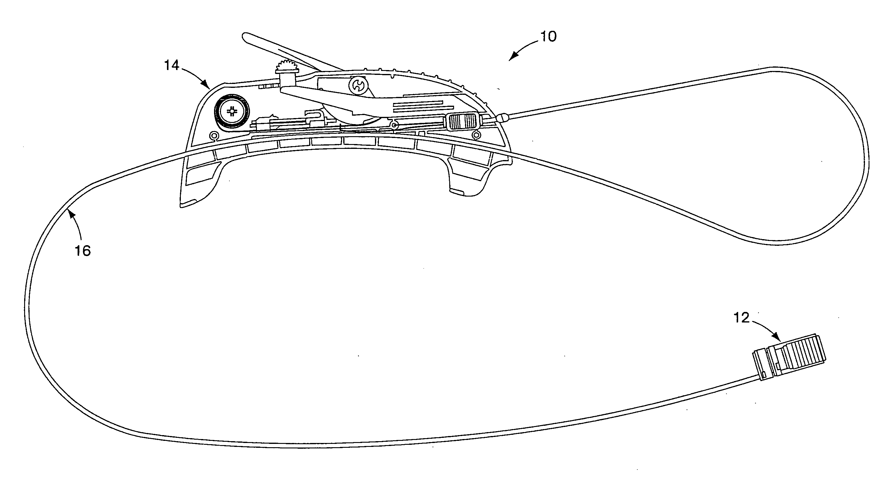
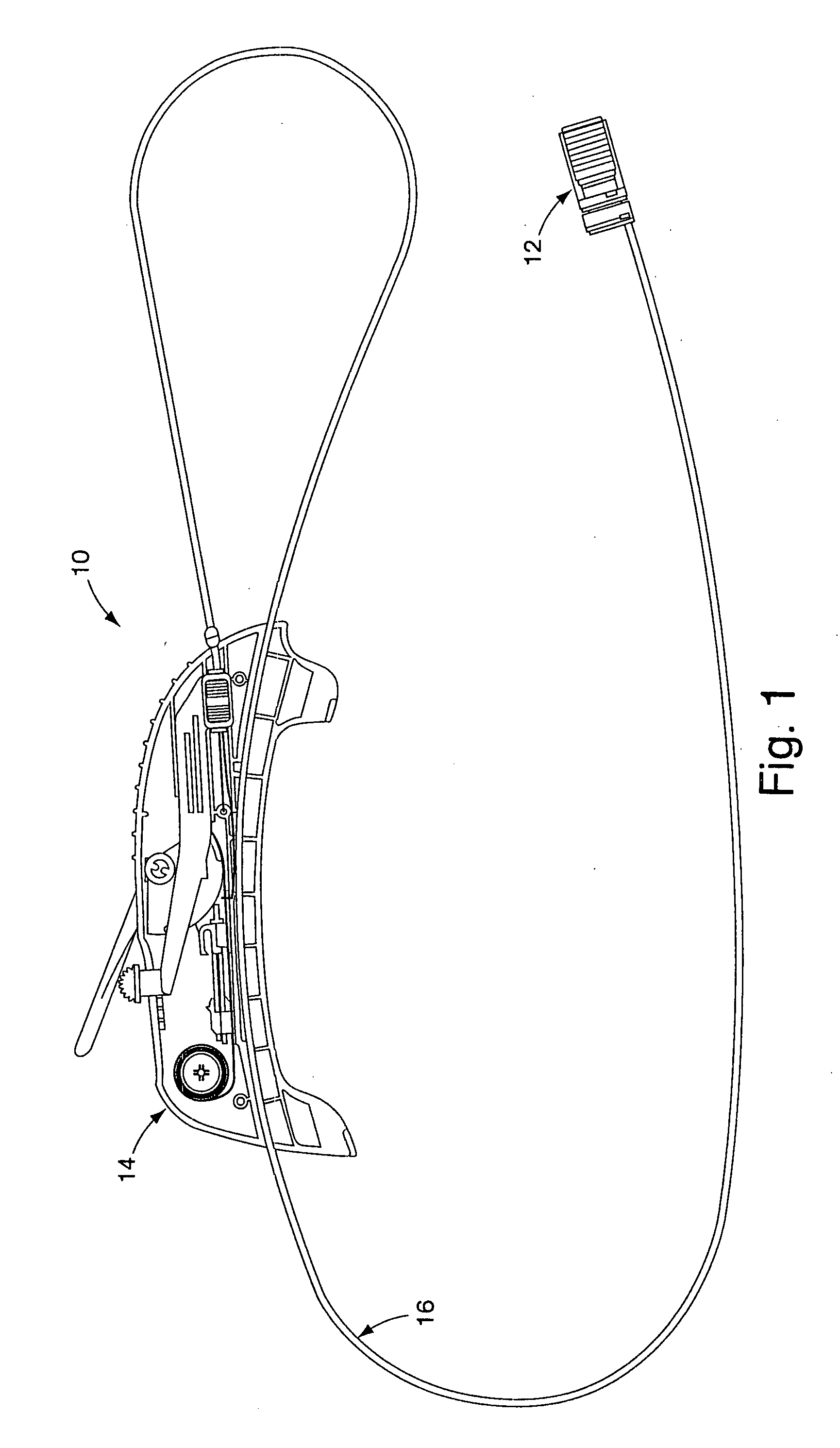
[0028] The endoscopic accessory control system 10, shown in FIG. 1, comprises an accessory distal operating portion 12 joined to a control handle 14 via a control sheath 16. The distal portion 12 is removably mounted to the distal end of an endoscope. The distal portion 12 shown in the figures and discussed in the illustrative embodiment is a multiple band endoscopic ligator configured to deliver ligating bands to internal tissue locations, such as at varices in order to prevent bleeding at those sites. It should be understood that other types of accessories such as forceps, cutting instruments or suturing devices could be substituted as the operating component 12 discussed here. The distal portion of the accessory is operated by control wires slidable through sheath 16, which extends proximally, external to the endoscope to the control handle 14. The handle is slidably and removably attached to the exterior of the endoscope shaft.

[0029] In an exemplary use of the band ligator devi...


PUM


Abstract

The present invention provides an endoscopic accessory control system that resides externally of the endoscope. The system comprises the endoscopic accessory with a working end to be placed at the distal end of the endoscope, a control sheath extending proximally external to the endoscope and a control handle joined to the proximal end of the control sheath. The control handle is slidably mounted to the exterior surface of the endoscope shaft and is configured to permit grasping of both the shaft and the handle. With the control handle and endoscope shaft grasped with one hand, the other hand of the user is left free to manipulate the endoscope distal tip controls. Additionally, the external arrangement of the control sheath leaves the working channel of the endoscope free for use of accessories or operations.

Description

FIELD OF THE INVENTION [0001] The present invention relates to endoscopes, accessory devices used with endoscopes and associated methods. In particular, the present invention is directed to facilitating use of medical devices and endoscopic accessories with an endoscope. BACKGROUND OF THE INVENTION [0002] Endoscopes are elongate instruments navigable through natural body lumens and cavities of a patient for the purpose of remotely evaluating and treating a variety of ailments. Endoscopes have viewing capability provided by fiber optic elements that transmit images along their length to the medical care provider. Endoscopes may specifically configured in length, diameter, flexibility and lumen configuration to navigate specific treatment areas in the body. Examples of specifically configured endoscopes are a laparoscope, duodenoscope, colonoscope, sigmoidoscope, bronchoscope and urethroscope among others. In combination with remote viewing capability, endoscopes are frequently config...

Claims


Application Information

Patent Timeline
Patent Type & Authority Applications(United States)
IPC IPC(8): A61B1/00A61B19/00A61BA61B1/012A61B1/018A61B17/00A61B17/12A61B17/32
CPCA61B1/00039A61B1/00087A61B1/00133A61B1/0014A61B2017/12018A61B17/12013A61B2017/00296A61B2017/00367A61B2017/0042A61B1/018A61B1/00042
Inventor ZIRPS, CHRISTOPHER T.MEMBRINO, TIMOTHY R.COPELAND, DAVID J.SILVA, SEAN J.MEARS, ERICLOGAN, JOSEPHYARDAN, STEPHEN J.
Owner CR BARD INC
Learn More