
Hub and spoke burner port configuration

a burner port and burner technology, applied in the direction of burners, extinguishing devices, combustion types, etc., can solve the problems of uneven cooking, uneven gas flow to all areas of the burner, uneven heat distribution,

Inactive Publication Date: 2008-07-03
ELECTROLUX HOME PROD CORP NV
View PDF79 Cites 19 Cited by
  • Summary
  • Abstract
  • Description
  • Claims
  • Application Information

AI Technical Summary

Benefits of technology

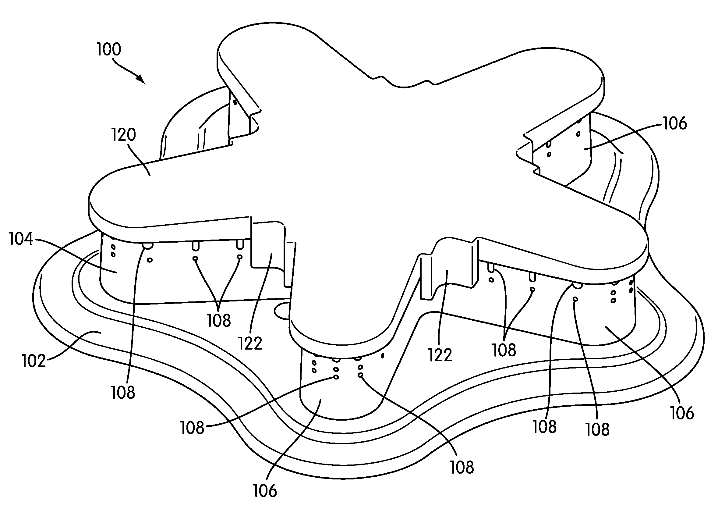
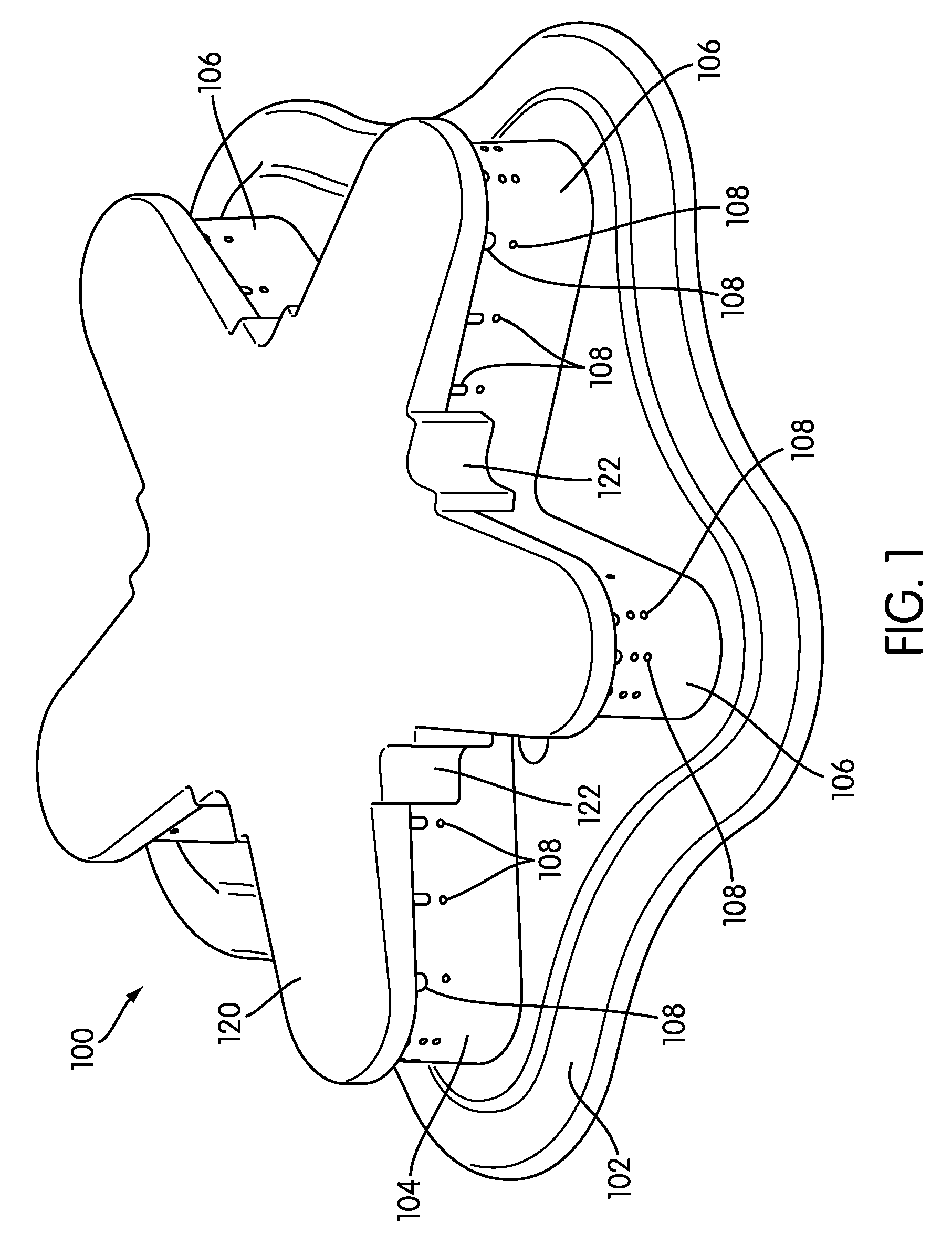
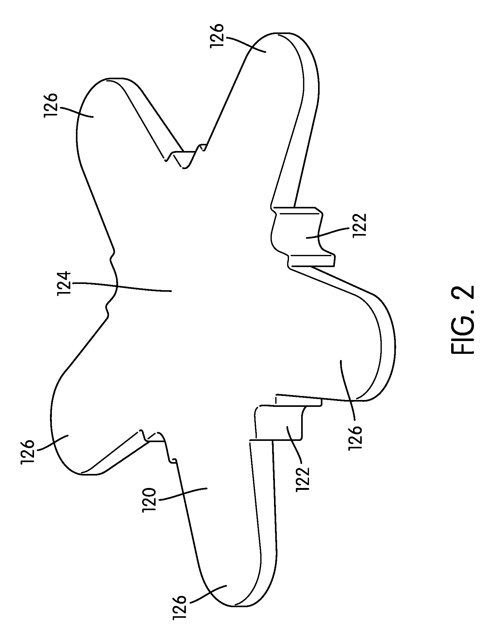
[0005]In accordance with the present disclosure, a burner assembly for a gas powered cooking appliance is provided. The burner assembly may include a burner body which is coupled to a gas supply via a burner base. The burner body may include a central region and a plurality of radiating extensions extending radially outward from the central region. In addition, the burner assembly may include a burner cap with a central region and a plurality of radiating extensions extending radially outward from the central region. The burner cap is positioned on top of the burner body when the burner is assembled and protects the interior portion of the burner assembly.
[0006]In one arrangement, the burner cap may include a plurality of overhangs positioned on the outer perimeter of the central region and between each of the radiating extensions. The overhangs form a gap between the exterior wall of the burner body and the interior wall of the overhang. This gap, or flame stabilization chamber, maintains a presence of flame to aid in maintaining the burner flame during low flow operation or in the event of a pressure change due to external forces.

Problems solved by technology

However, circular gas burners provide heat only at a circular perimeter of the burner flame.
This arrangement may lead to uneven heat distribution and / or uneven cooking.
Alternate burner shapes have been developed, however, providing even gas flow to all areas of the burner is difficult.
In addition, gas burners are often sensitive to air pressure changes due to environmental conditions, such as a cupboard or oven door opening or closing.
Changes in pressure may cause the burner flame to extinguish.
Such pressure changes are particularly problematic at low temperature settings because the flow of gas to the burner has less velocity than at high temperature settings, making the flame less stable.

Method used


Image

  • Hub and spoke burner port configuration
  • Hub and spoke burner port configuration
  • Hub and spoke burner port configuration

Examples


Embodiment Construction

[0016]The following discussion and accompanying figures disclose a burner assembly for use with a gas powered cooking appliance. The burner assembly arrangement described may be incorporated into any conventional gas powered stove or cooktop. For ease of understanding, the burner assembly will be described as being incorporated into a gas stove. In addition, the term gas generally refers to a cooking fuel that includes a mixture of natural gas and air. Additionally or alternatively, the cooking fuel used may be propane, butane, manufactured gas, and the like.

[0017]A burner assembly 100 according to aspects of the disclosure is shown in FIG. 1. The burner assembly 100 generally includes a burner base (not shown) that is coupled to a gas supply and a valve. The burner base protrudes through the top of the stove and is connected to a burner body 104. In an alternate arrangement, a burner skirt 102 may be included on the top of the stove and the burner base may protrude therethrough. It...


PUM


Abstract

A burner assembly for a gas powered cooking appliance is provided. The burner assembly may include a burner body including a central region and a plurality of radiating extensions extending radially outward from the central region. The burner assembly may include a burner cap with a central region and a plurality of radiating extensions extending radially outward from the central region. The burner cap is positioned on top of the burner body when the burner is assembled. The burner cap may include at least one overhang positioned on the outer perimeter of the central region and between an adjacent pair of radiating extensions. The at least one overhang forms a gap between the exterior wall of the burner body and the interior wall of the overhang. This gap, or flame stabilization chamber, provides for collection of gases and flame that aid in maintaining the flame during low temperature operation.

Description

CROSS REFERENCE TO RELATED APPLICATIONS[0001]This application claims priority to U.S. Provisional Application No. 60 / 882,658, filed Dec. 29, 2006, entitled “Hub and Spoke Burner with Flame Stability and Port Configuration” and expressly incorporated herein by reference.TECHNICAL FIELD[0002]This application deals with a burner arrangement for a cooking appliance. More specifically, this application deals with a burner cap and burner port configuration that aids in providing flame stability for a gas burner on a stove or cooktop.BACKGROUND[0003]Conventional stoves, as used in home or commercial kitchens, are often gas powered. Cooking with gas provides an efficient cooking method while also providing good temperature control for the cook. In some conventional systems, a circular gas burner has been used to ensure consistent flow to all areas of the burner. However, circular gas burners provide heat only at a circular perimeter of the burner flame. This arrangement may lead to uneven h...

Claims


Application Information

Patent Timeline
IPC IPC(8): F23Q2/50
CPCF23D14/06F23D2900/14064F23D14/58F23D14/26
Inventor PRYOR, WILLIAM MICHAELDONASTORG, HECTOR JOSEPOTTENGER, JOHN THURLPADGETT, MICHAEL DENNIS
Owner ELECTROLUX HOME PROD CORP NV
Learn More