
Detection of wheel positions and detection of tire inflation pressure

a technology for detecting wheel positions and tire inflation pressure, which is applied in the direction of tire measurement, vehicle components, signalling/lighting devices, etc., can solve the problems of tire inflation pressure detecting apparatus not being able to cope with the position change of wheels, the position of individual transceivers in the vehicle cannot be detected, and the intensity of lf waves is weak

Inactive Publication Date: 2008-07-03
DENSO CORP
View PDF7 Cites 21 Cited by
  • Summary
  • Abstract
  • Description
  • Claims
  • Application Information

AI Technical Summary

Benefits of technology

[0013]The present invention has been made in light of the circumstances described above and has as its object to provide a wheel position detecting apparatus which is able to detect the correlation of the transceivers with the wheels on which the transceivers are installed, without the need of performing readout, for example, of the ID information by the user. In particular, the present invention has an object of providing a wheel position detecting apparatus having compatibility to vehicles regardless of the types of the vehicle and is capable of conducting high-speed wheel position detection with reliability.
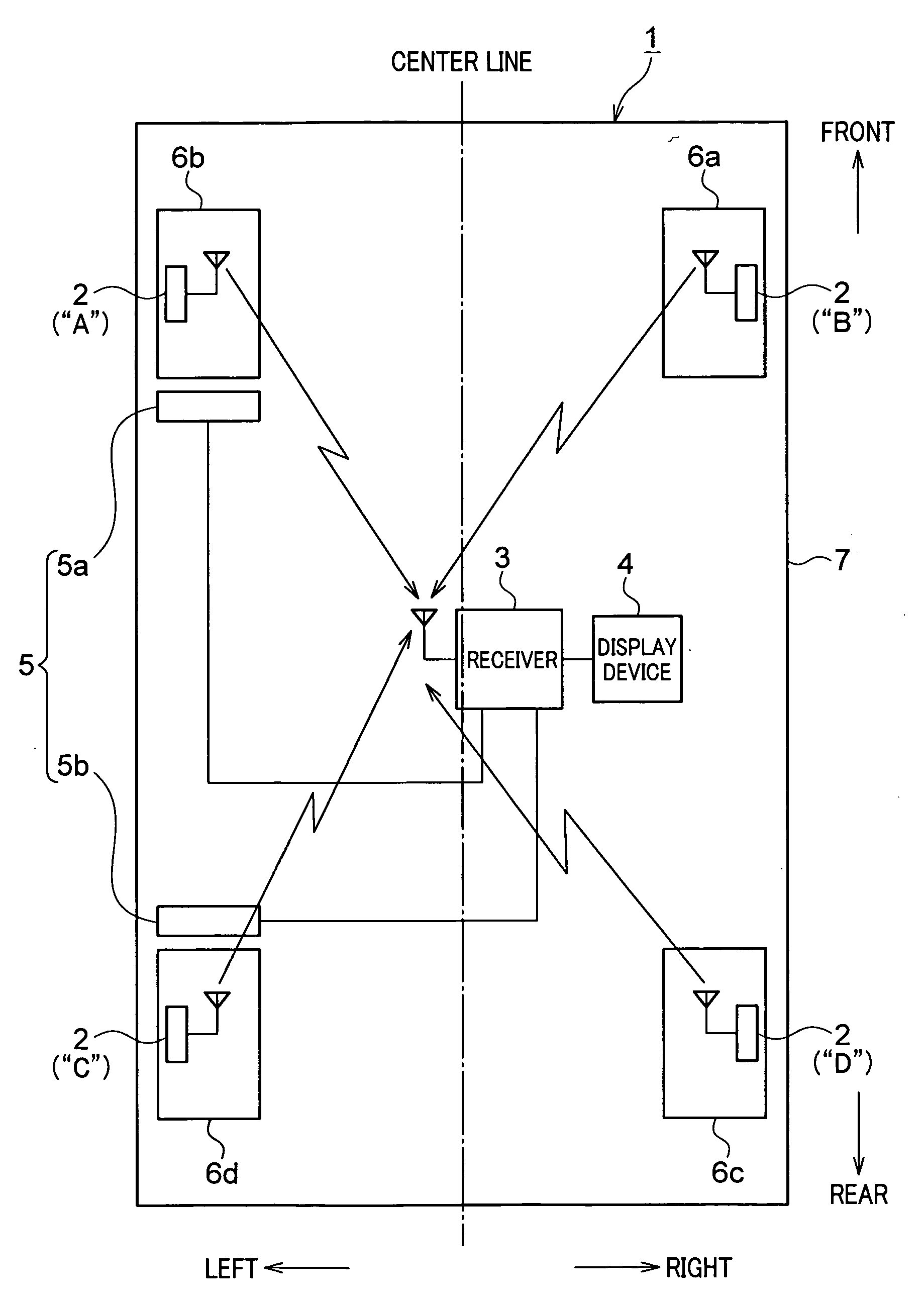
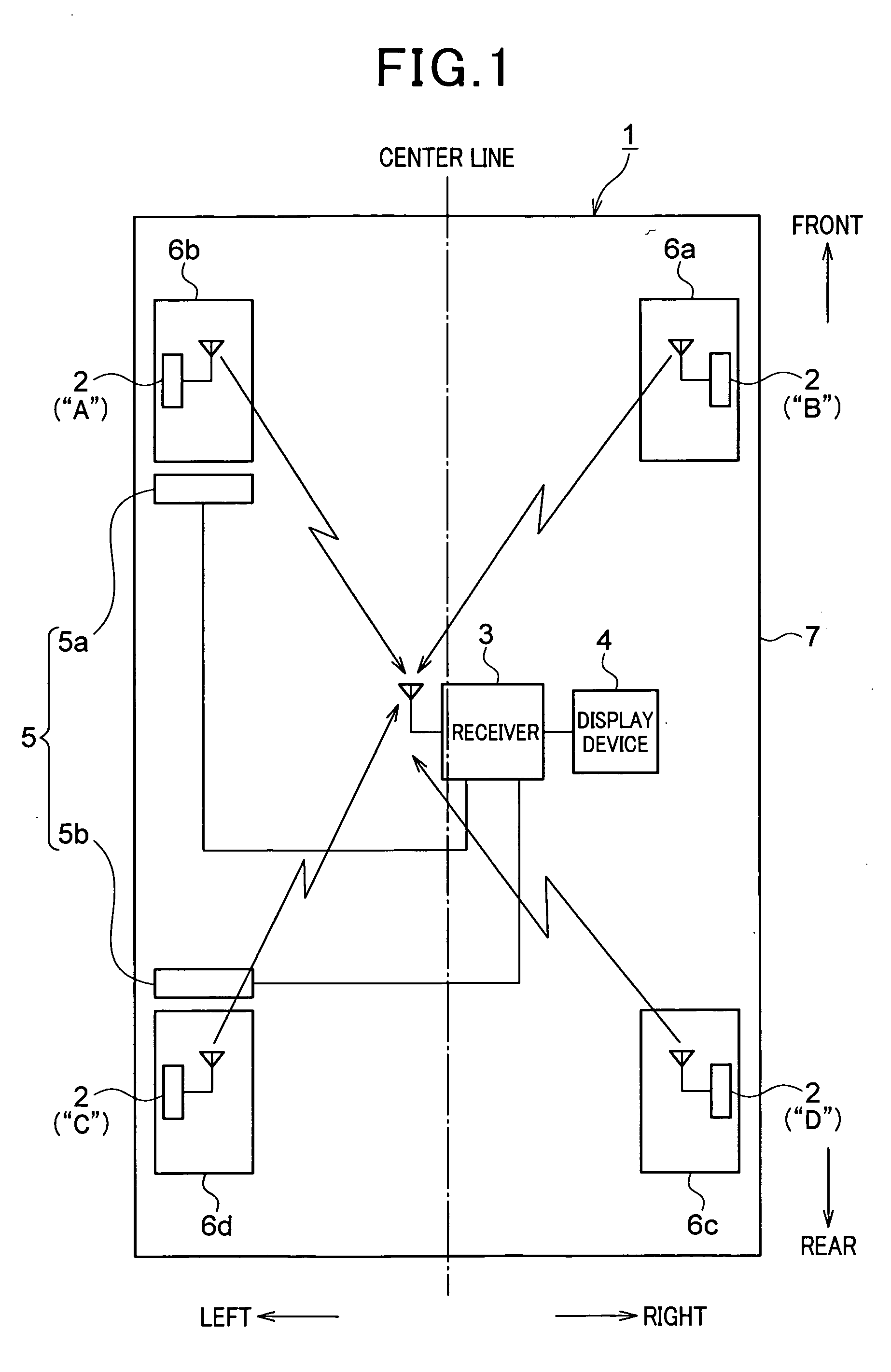
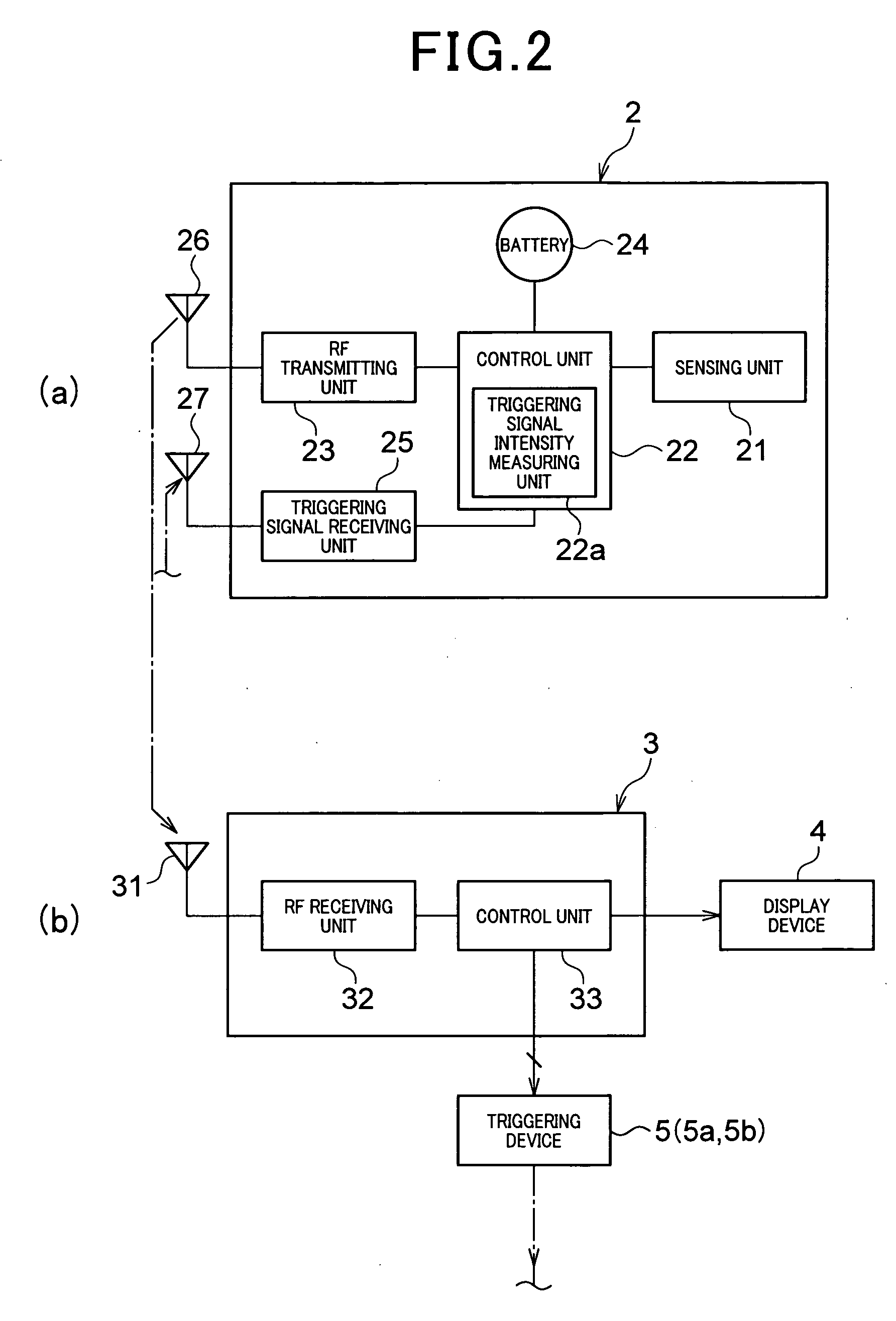
[0015]Thus, the triggering signals outputted from the first triggering device are adapted to reach the two transceivers installed on the left- and right-front wheels, while the triggering signals outputted from the second triggering device are adapted to reach the two transceivers installed on the left- and right-rear wheels. The individual transceivers are then started up by the startup commands and allowed to measure the reception intensities of the triggering signals by the execution commands contained in the triggering signals. Further, the transceivers installed on the respective wheels are ensured to be identified by utilizing the property that the intensity of a triggering signal becomes lower as the distance from the first and second triggering devices to each of the transceivers becomes larger. Thus, the individual transceivers can be reliably started up by the output of the triggering signals from the first and second triggering devices. At the same time, immediately after the startup, processes for wheel position detection can be reliably executed. Accordingly, prompt and reliable wheel position detection can be achieved without the necessity of having the triggering signals outputted repeatedly. In particular, performing wheel position detection by starting up the individual transceivers immediately after turning the ignition switch from an off-state to an on-state, will enable wheel position detection before traveling, or enable reliable tire inflation pressure detection before traveling. In addition, high flexibility may be achieved in the design because the triggering signals outputted from the first and second triggering devices may only have to be reliably transmitted to the transceivers installed on the left and right wheels. Also, comparing with the case of using noises, high compatibility to vehicles can be achieved.
[0016]In this mode of the invention, the first and second triggering devices are desirably disposed being offset in the same direction from a center line which symmetrically divides the vehicle body left and right. In the case where triggering signals are outputted from the first triggering device, use of such an offset arrangement may enable the receiver to identify the wheel, for example, in the left- and right-front wheels, which are located closer to the first triggering device, based on the reception intensity data stored in the frames transmitted from the associated transceivers. Similarly, in the case where triggering signals are outputted from the second triggering device, use of such an offset arrangement may enable the receiver to identify the wheel, for example, in the left- and right-rear wheels, which are located closer to the second triggering device, based on the reception intensity data stored in the frames transmitted from the associated transceivers. Further, the wheel which is located further from the first triggering device in the left- and right-front wheels can be identified, based on the reception intensity data stored in the frames transmitted from the associated transceivers in the case where the triggering signals are outputted from the first triggering device. Similarly, the wheel which is located further from the second triggering device in the left- and right-rear wheels can be identified, based on the reception intensity data stored in the frames transmitted from the associated transceivers in the case where the triggering signals are outputted from the second triggering device. In this way, the four transceivers installed on the respective wheels can be identified.
[0018]In the first mode of the present invention, wheel position detection has been conducted by allowing the first triggering device to output triggering signals to the left- and right-front wheels, and allowing the second triggering device to output triggering signals to the left- and right-rear wheels. However, as exemplified in the second mode of the invention, wheel position detection can also be conducted by allowing is the first triggering device to output triggering signals to the two right wheels, and allowing the second triggering device to output triggering signals to the two left wheels. In this mode as well, advantages similar to those of the first mode of the invention can be obtained.
[0019]In the second mode of the invention, the first and second triggering devices are desirably disposed being offset in the same direction from the center line which symmetrically divides the vehicle body front and rear. In the case where triggering signals are outputted from the first triggering device, use of such an offset arrangement may enable the receiver to identify the wheel, for example, in the two right wheels, which is located closer to the first triggering device, based on the reception intensity data stored in the frames transmitted from the associated transceivers. Similarly, in the case where triggering signals are outputted from the second triggering device, use of such an offset arrangement may enable the receiver to identify the wheel, for example, in the two left wheels, which is located closer to the second triggering device, based on the reception intensity data stored in the frames transmitted from the associated transceivers. Further, the wheel which is located further from the first triggering device in the two right wheels can be identified, based on the reception intensity data stored in the frames transmitted from the associated transceivers in the case where the triggering signals are outputted from the first triggering device. Similarly, the wheel which is located further from the second triggering device in the two left wheels can be identified, based on the reception intensity data stored in the frames transmitted from the associated transceivers in the case where the triggering signals are outputted from the second triggering device. In this way, the four transceivers installed on the respective wheels can be identified.

Problems solved by technology

In other words, without using the ID information, the positions of the individual transceivers in the vehicle cannot be detected.
Without doing this, the tire inflation pressure detecting apparatus cannot cope with the position change of the wheels.
Further, the larger the distance is from the generation source of the LF waves to the destination, the weaker the intensity of the LF waves become.
These relationships are very difficult to be established.
Even if there is a design that can establish such relationships, the design may have poor flexibility.
In addition, even if such relationships can be established, it will take time for calculating the reception rates of the LF waves at the transceivers for the left- and right-front wheels and the reception rates of the LF waves at the transceivers for the left- and right-rear wheels.
This may also involve a difficulty, for example, of reliably detecting the wheel positions before traveling.
The apparatus disclosed in U.S. Pat. No. 6,888,446 has poor compatibility with vehicles because the noise generation sources are different depending on the types of the vehicles.
In other words, this apparatus has a difficulty in achieving good compatibility with vehicles regardless of the types of the vehicles.
In particular, in the case where wheel position detection is carried out merely based on noises, the apparatus cannot cope with such noises that are produced by devices loaded on the vehicle according to the user's taste.
Further, the timing of each of the noises that are considered to be produced during the on-state of the ignition switch cannot be estimated.
Therefore, it is not easy to simultaneously transmit triggering signals to all of the transceivers for the purpose of wheel position detection.
For this reason, it will take a long time to conduct the wheel position detection, or it will be difficult, for example, to reliably conduct wheel position detection before traveling.

Method used


Image

  • Detection of wheel positions and detection of tire inflation pressure
  • Detection of wheel positions and detection of tire inflation pressure
  • Detection of wheel positions and detection of tire inflation pressure

Examples


first embodiment

[0034]A first embodiment of the present invention will now be described referring to the drawings. FIG. 1 is a block diagram generally illustrating a tire inflation pressure detecting apparatus, in which a wheel position detecting apparatus is applied, according to a first embodiment of the present invention. A direction toward an upper portion of the drawing sheet of FIG. 1 corresponds to a frontward direction of a vehicle 1, and a direction toward a lower portion of the drawing sheet of FIG. 1 corresponds to a rearward direction of the vehicle 1. Referring to FIG. 1, a tire inflation pressure detecting apparatus according to the present invention is described.

[0035]As shown in FIG. 1, the tire inflation pressure detecting apparatus, which is or is to be mounted on a vehicle 1, includes four transceivers 2 (i.e., each serves as a transmitter / receiver), a receiver 3, a display device 4, and triggering devices 5. In the present embodiment, the transceivers 2, the receiver 3, and the ...

second embodiment

[0088]Hereinafter will be described a second embodiment of the present invention. In the first embodiment described above, the triggering signals outputted from the first triggering device 5a have been received by only the transceivers 2 installed on the left- and right-front wheels 6a and 6b, while the triggering signals outputted from the second triggering device 5b have been received by only the transceivers 2 installed on the left- and right-rear wheels 6c and 6d. However, there is a possibility that the triggering signal outputted from the first triggering device 5a may also be received by the transceiver 2 installed on the left-rear wheel 6d, or the triggering signal outputted from the second triggering device 5b may also be received by the transceiver 2 installed on the left-Front wheel 6b. The present embodiment may enable reliable wheel position detection under such conditions. A tire inflation pressure detecting apparatus provided with the wheel position detecting apparatu...

third embodiment

[0111]Hereinafter will be described a third embodiment of the present invention. The third embodiment is different from the first embodiment in that it has another arrangement of the first and second triggering devices 5a and 5b.

[0112]FIG. 9 is a pattern diagram illustrating an arrangement of the first and second triggering devices 5a and 5b. As shown in the figure, the first triggering device 5a is arranged, as in the first embodiment, being offset from the center line of the vehicle 1 and being closer to the left-front wheel 6b than to the right-front wheel 6a. The second triggering device 5b is arranged also being offset from the center line of the vehicle 1 but, unlike the first embodiment, being closer to the right-rear wheel 6c than to the left-rear wheel 6d. Specifically, it is so arranged that a diagonal positional relationship is established between the left-front wheel 6b in the two front wheels 6a and 6b, which is located close to the first triggering device 5a, and the ...


PUM


Abstract

In a vehicle's wheel position detecting apparatus, plural transceivers respectively attached to the front and rear four wheels are provided. Each transceiver receives a triggering signal, calculates a reception intensity of the triggering signal, stores data indicating the reception intensity into a frame, and transmits the frame to a receiver attached to a vehicle's body. Each triggering signal radio-transmitted from the first and second triggering devices contains a startup command to starts up each transceiver and an execution command to allow each transceiver to calculate the reception intensity. The first and second triggering devices, which are responsible for radio-transmitting the triggering signal toward at least the front wheels and the rear wheels respectively, are positionally offset to either way in the body's lateral direction. A receiver receives the frames and uses the frames radio-transmitted from the transceivers to detect the wheels' positions using the reception intensity in each frame.

Description

CROSS-REFERENCE TO RELATED APPLICATION[0001]This application is based on and claims the benefit of priority from earlier Japanese Patent Application No. 2006-356829 filed Dec. 29, 2006, the description of which is incorporated herein by reference.BACKGROUND OF THE INVENTION[0002]1. Field of the Invention[0003]The present invention relates to an apparatus for detecting the wheel positions of a vehicle, on which respective wheels are installed, an apparatus for detecting the inflation pressure of the tires of a vehicle, such as a direct-type tire inflation pressure detection apparatus, and transceivers therefor.[0004]2. Description of the Related Art[0005]A direct-type apparatus for detecting the inflation pressure of tires of a vehicle is known. This tire inflation pressure detecting apparatus is provided with a transceiver equipped with a sensor such as a pressure sensor, which is directly installed on each wheel with a tire. An antenna and a receiver are provided in the vehicle bod...

Claims


Application Information

Patent Timeline
IPC IPC(8): B60Q1/00
CPCB60C23/0416B60C23/0442B60C23/045B60C23/0444B60C23/0462B60C23/00B60C23/02
Inventor MORI, MASASHIWATABE, NOBUYA
Owner DENSO CORP
Learn More