
Sensing Device

a technology of sensing device and sensor, which is applied in the direction of vibration measurement in solids, generator/motor, instruments, etc., can solve the problems of unexpectedly high analysis cost, very expensive measurement device, and very strong toxicity to human body, so as to avoid overlapping of mutual spectrum, reduce cost, and simple circuit configuration

Active Publication Date: 2008-07-03
NIHON DEMPA KOGYO CO LTD
View PDF18 Cites 17 Cited by
  • Summary
  • Abstract
  • Description
  • Claims
  • Application Information

AI Technical Summary

Benefits of technology

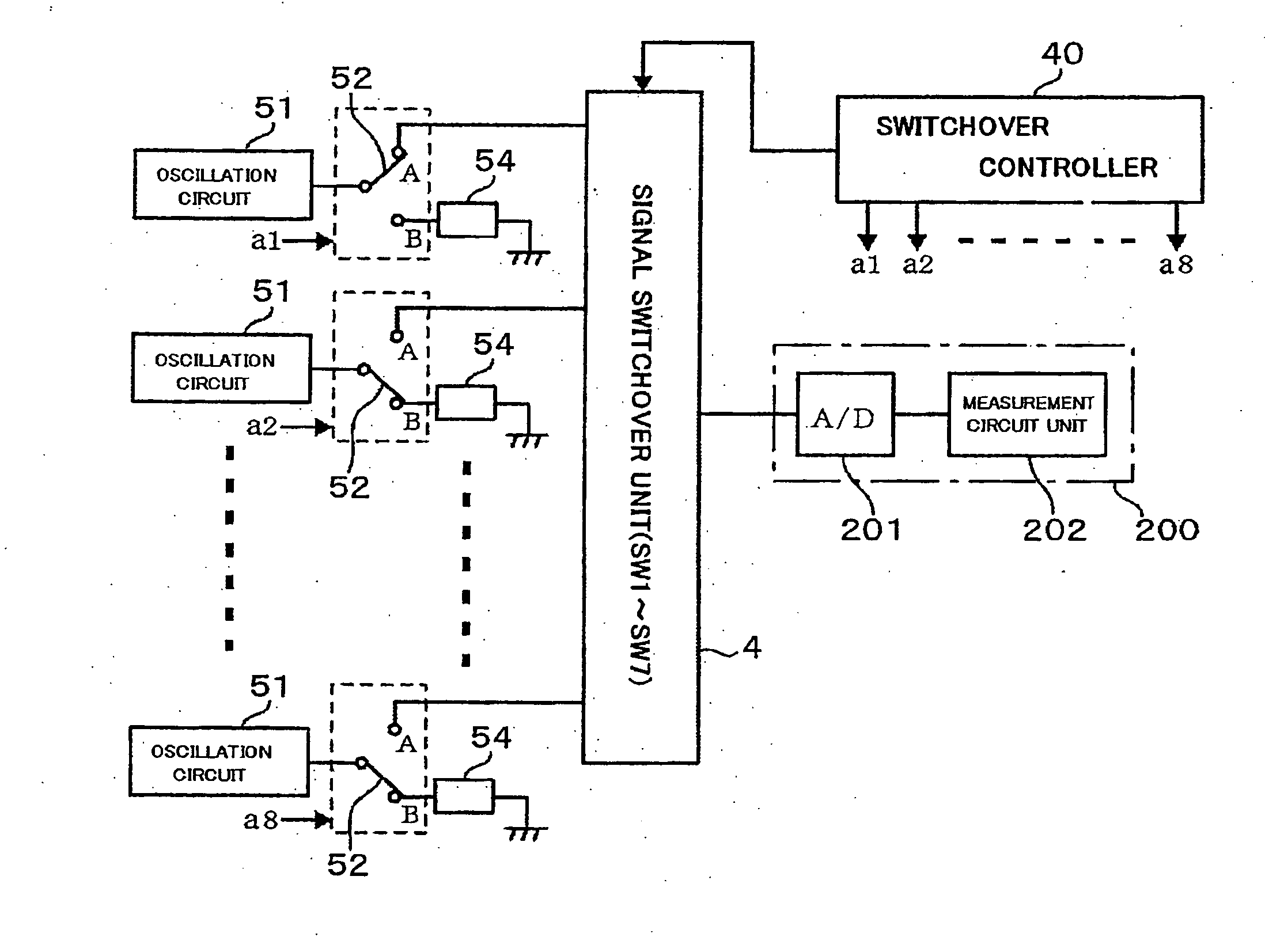
[0018]According to the present invention, when a plurality of sensor resonators, for instance, quartz resonators of which natural frequency changes due to adsorption of an object to be detected, a common measuring unit to measure the change of the frequency is provided for each oscillation circuit corresponding to each sensor resonator so as to perform switchover connection in turn, and is structured in a manner that the terminal loads of the oscillation circuit connected to the measuring unit are the first values, and the terminal loads of the oscillation circuits selected from among the oscillation circuit not connected to the measuring unit, for instance, the terminal loads of all oscillation circuits not connected to the measuring unit are the second values. Therefore, it is possible to avoid overlapping of mutual spectrum by forcibly separating the mutual oscillation frequencies of the sensor resonator from each other. Accordingly, it is possible to perform detection of the object (measurement of concentration and measurement of the presence or absence of the object to be detected) in a stable fashion. Furthermore, since the measuring unit is used in common for a plurality of sensor resonators, the circuit configuration is simple, so that the cost reduction can be realized.

Problems solved by technology

There are some pollutants which have very strong toxicity to the human body even with a very small quantity.
Although it is possible to perform highly accurate microanalysis of the order of 10−22 g / ml by gas chromatography mass spectrometry, the method has disadvantages in that the measurement device is very costly, which makes the cost of analysis unexpectedly expensive, and furthermore, it takes a long time for results to be known.
In the meantime, the ELISA method is cheaper in price for the equipment and analysis, and less time consuming, compared with the gas chromatography mass spectrometry, but it has the disadvantage of low accuracy of the order of 10−9 g / ml.
When measurement is conducted using many quartz sensors, there exists the following disadvantage.
That is, although the oscillation frequency of a quartz resonator is determined by the design value, it is practically impossible for actual products to make each oscillation frequency precisely identical to one another.
It is also practically impossible to form adsorbing layers with absolutely the same size and thickness on the electrode surfaces.
Accordingly, when the distance between respective quartz sensors is small, in other words, when the distance between the quartz sensors adjacent each other, these quartz sensors are spatially connected so that the oscillation frequencies become unstable affected by mutual frequencies.
This phenomenon resembles to that when antennas are brought closer together, the oscillation frequency becomes unstable, which makes it impossible to measure the frequency accurately.
Therefore, it becomes difficult to detect the object, in other words, it becomes difficult to measure the exact concentration of the object or to detect the presence or absence of the object in very small quantities with a high degree of accuracy. FIG. 11 shows an example of the situations that between quartz sensors which are close to each other, one spectrum relating to the measurement overlaps with the other spectrum relating to the measurement.
Though it is possible to avoid such phenomena by making the distance between respective quartz sensors greater, this can result in the device being too large.
When a large number of the quartz sensors are used, the device cannot be minimized sufficiently and it departs from the market demand unless they are arranged in a closely packed fashion.

Method used


Image

  • Sensing Device
  • Sensing Device
  • Sensing Device

Examples


Embodiment Construction

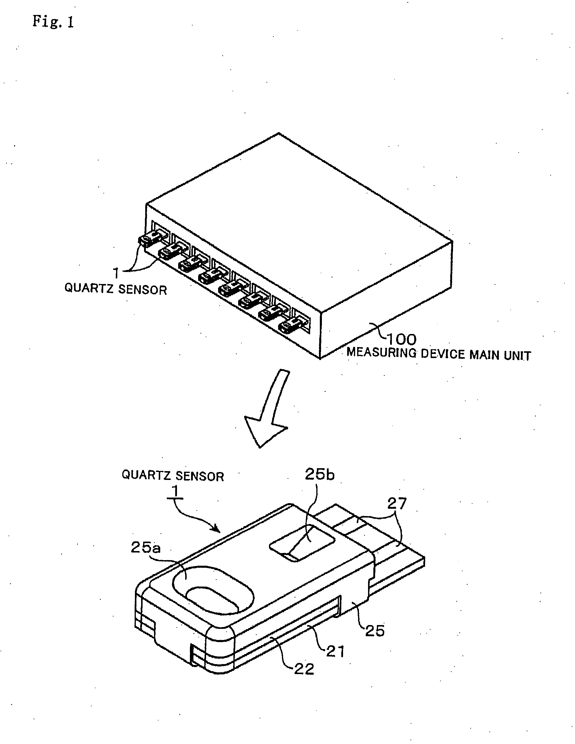
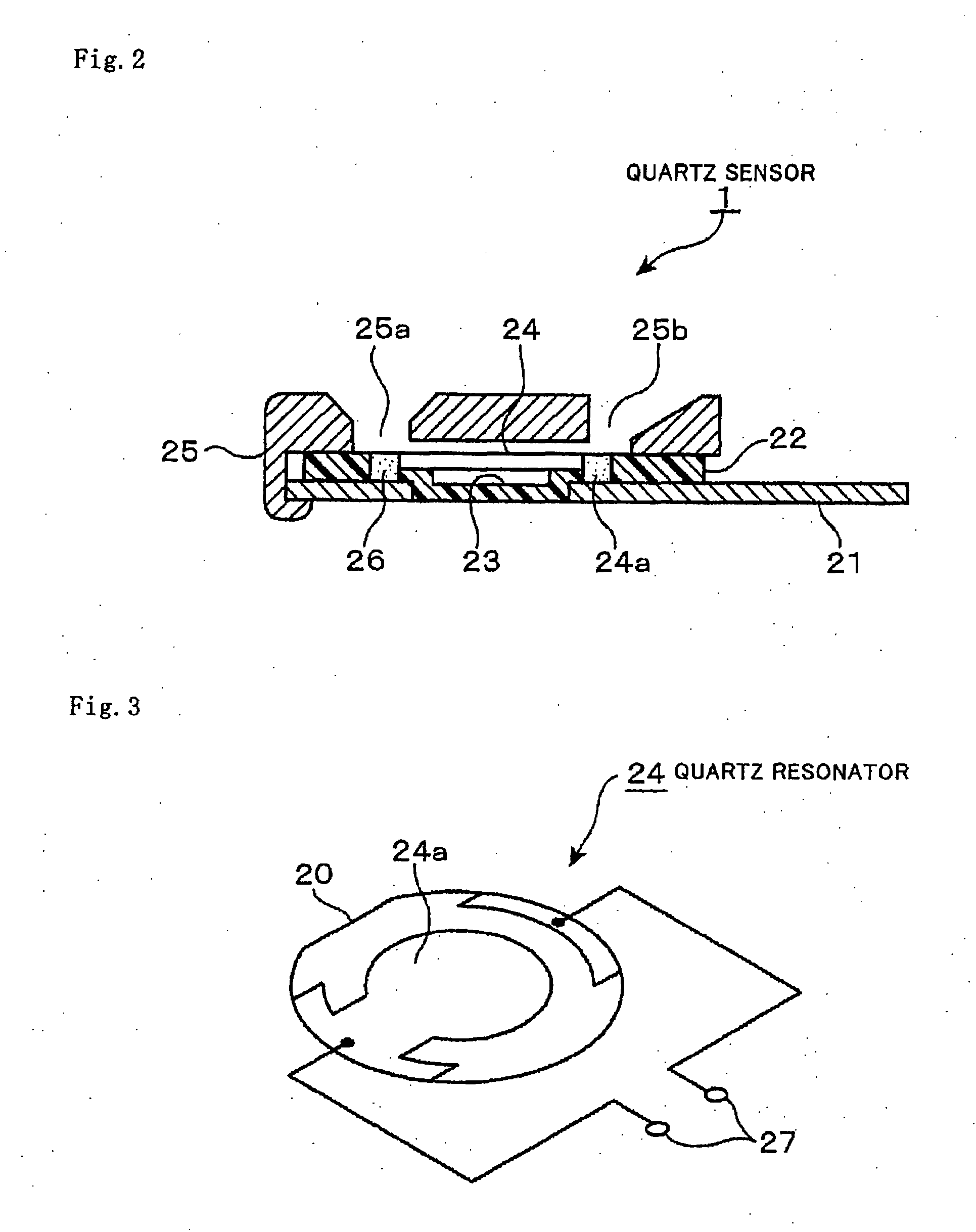
[0030]Hereinafter, an embodiment of a sensing device relating to the present invention will be explained. Though the present embodiment has a principal portion in the rear circuit part of an oscillation circuit, the whole structure will be explained briefly first. The sensing device includes a quartz sensor 1 composed of a plurality of, for instance 8 pieces of, sensor units; and a measurement device main unit 100 to which the quartz sensor 1 is detachably installed, as shown in FIG. 1. As shown in FIG. 1 and FIG. 2, the quartz sensor 1 is structured in a manner that a rubber sheet 22 is placed upon a printed circuit board 21 which is a wiring board, a quartz resonator 24 is placed to cover a recess 23 arranged in the rubber sheet 22, and an upper lid case 25 is mounted on the rubber sheet 22. The printed circuit board 21 and the rubber sheet 22 serve as a holding member, and the quartz resonator 24 corresponds to a sensor resonator. A pouring opening 25a of a sample solution and an...


PUM


Abstract

An object of the present invention is to avoid the instability of frequency measurement caused by spatial connection between quartz sensor adjacent to each other when a plurality of quartz sensors including a quartz resonator which varies the national frequency due to adsorption of an object to be detected. As a concrete means for solving the problem is to provide a common measuring unit 200 to measure the variation in frequency to each oscillation circuit 51 corresponding to each quartz sensor 1 so as to switchover and connect in turn, and as for the oscillation circuits 51 excepting the oscillation circuits 51 connected to the measuring unit 200 by the switches 52 serving as the load switchover unit, the load value on the output side of the oscillation circuit 51 included (relating to the measurement) in the channels connected to the measuring unit 200 and the load value on the output side of the standby oscillation circuits 51 are made different from each other, so that the respective oscillating frequencies are forcibly separated from each other.

Description

TECHNICAL FIELD[0001]The present invention relates to a sensing device that uses a resonator, e.g. a quartz resonator, which has an adsorbing layer for adsorbing an object to be detected on the surface of the resonator and changes the natural frequency thereof by adsorbing of the object, and senses the object by detecting the variation in the natural frequency of the sensor resonator.BACKGROUND ART[0002]The necessity to know the concentration of various pollutants in a river or soil has been increasing for the purpose of maintaining environmental preservation. There are some pollutants which have very strong toxicity to the human body even with a very small quantity. Consequently, the establishment of measurement technology for the pollutants in a very small quantity has been expected. Dioxin is one of the pollutants on which much attention has been recently focused and methods of using a gas chromatography mass spectrometer and Enzyme-Linked Immuno Sorbent Assay (ELISA) are known a...

Claims


Application Information

Patent Timeline
IPC IPC(8): G01N5/02G01H13/00
CPCG01N5/02G01N29/022G01N2291/0256G01N29/222G01N2291/0255G01N29/036
Inventor ONISHI, NAOKISHIOBARA, TSUYOSHI
Owner NIHON DEMPA KOGYO CO LTD
Learn More