
Energy-Absorbing Liners and Shape Conforming Layers for Use with Pro-Tective Headgear

a protective headgear and shape-conforming technology, applied in the field of protective headgear, can solve the problems of affecting the safety of users, so as to improve user fit and comfort, and reduce the weight of protective headgear without compromising user safety

Inactive Publication Date: 2008-07-03
XENITH
View PDF50 Cites 108 Cited by
  • Summary
  • Abstract
  • Description
  • Claims
  • Application Information

AI Technical Summary

Benefits of technology

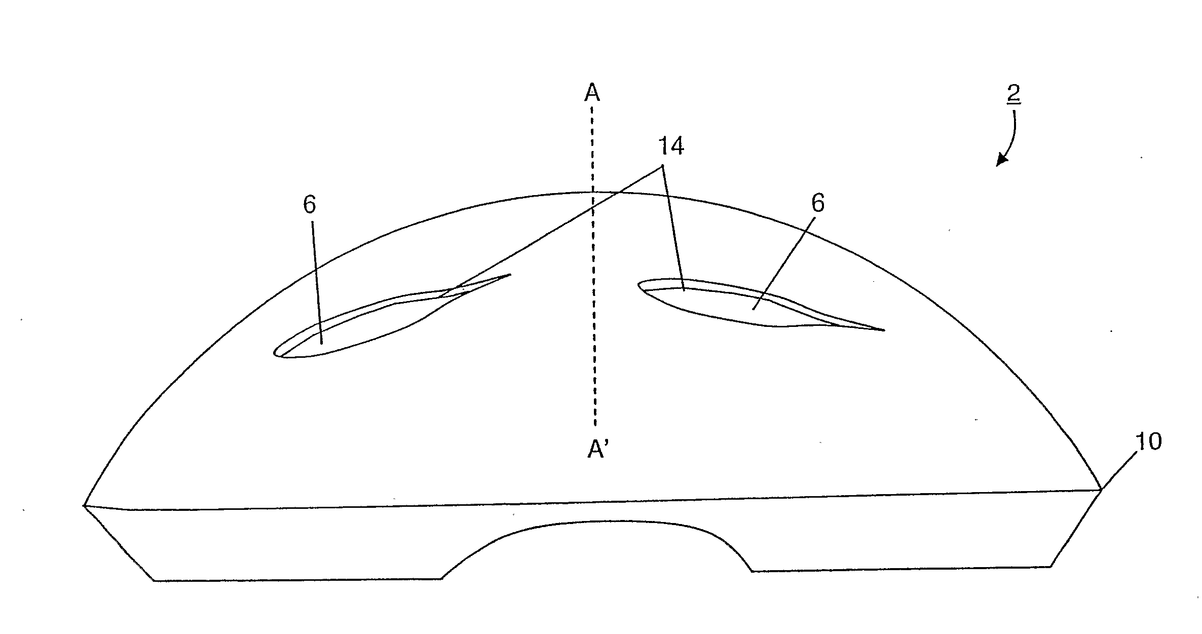
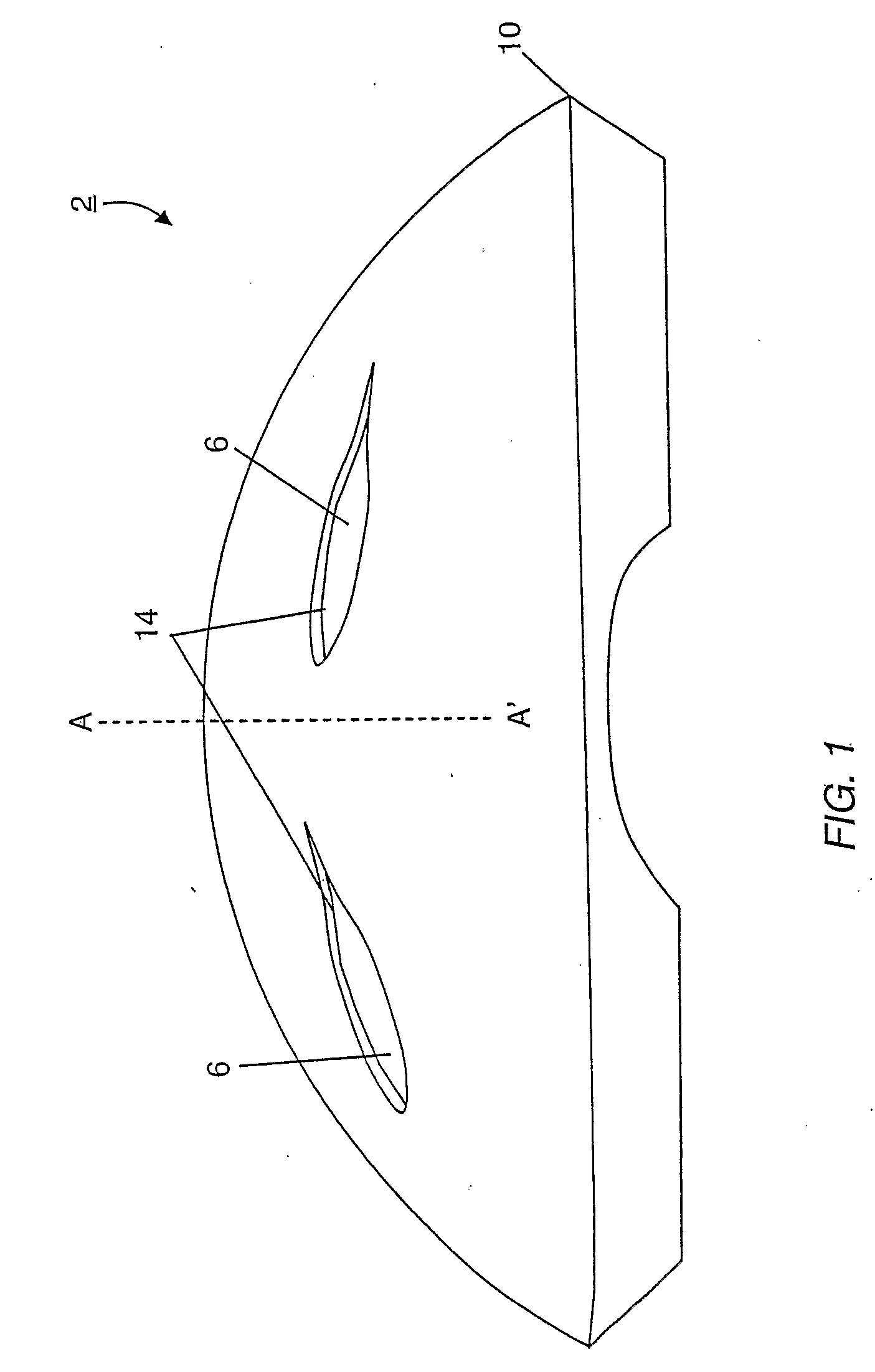
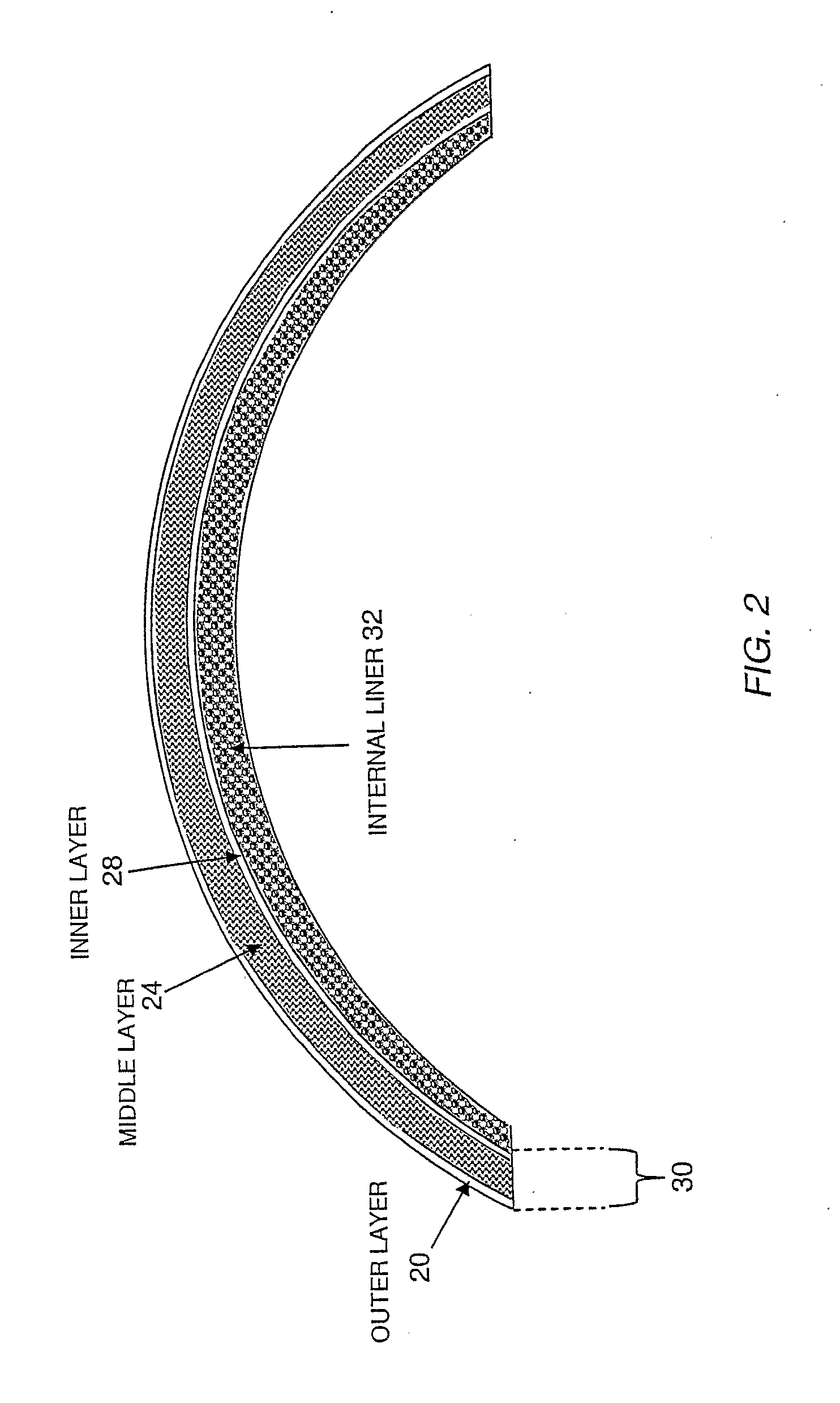
[0011]In another aspect, the invention features protective headgear comprising an outer layer having an internally facing surface, an inner layer having a surface that faces the outer layer, and a middle layer having a plurality of compressible members disposed in a fluid-containing interstitial region bounded by the inner and outer layers, and an internal liner layer disposed inwardly of the inner layer. The inner layer has an open configuration or a non-continuous form. The internal liner layer is formed of contouring materials which enhance user fit and comfort and reduce the weight of the protective headgear without compromising user safety.

Problems solved by technology

Concussions, also called mild traumatic brain injury, are a common, serious problem in sports known to have detrimental effects on people in the short and long term.
Although concussions are prevalent among athletes, the study of concussions is difficult, treatment options are virtually non-existent, and “return-to-play” guidelines are speculative.
Concussion results from a force being applied to the brain, usually the result of a direct blow to the head, which results in shearing force to the brain tissue, and a subsequent deleterious neurometabolic and neurophysiologic cascade.
A thick inner layer, however, requires a corresponding increase in the size of the outer shell, which increases the size and bulkiness of the helmet.
Materials that rebound too quickly, however, permit some of the kinetic energy of the impact to transfer to the wearer's head.
The drawback of a thick layer, as noted above, is the resulting bulkiness of the helmet.
Moreover, the energy absorbing properties of such materials tend to diminish with increasing temperatures, whereas the positive rebound properties diminish with decreasing temperatures.

Method used


Image

  • Energy-Absorbing Liners and Shape Conforming Layers for Use with Pro-Tective Headgear
  • Energy-Absorbing Liners and Shape Conforming Layers for Use with Pro-Tective Headgear
  • Energy-Absorbing Liners and Shape Conforming Layers for Use with Pro-Tective Headgear

Examples


third embodiment

[0085]FIG. 14 illustrates the internal liner layer 32 wherein the liner is provided with a geodesic dome shape having triangular shaped cutouts. Stated another way, in this configuration, the lines of the thermoplastic are formed into triangles which meet at the vertices.

fourth embodiment

[0086]FIG. 15 illustrates the internal liner layer 32 wherein the liner is non-continuous and is provided with a honeycomb, wherein the liner defined hexagonal shapes. Still other examples of inner liner configurations will be recognized by those skilled in the art, including combinations of the described patterns.


PUM


Abstract

A multilayer shell for use in the construction of protective headgear, the shell including an outer layer, an inner layer, a middle layer disposed between the outer and inner layer which resiliently compresses in response to an impact to the outer layer, and an internal liner disposed inwardly of the inner layer. The middle layer includes a plurality of compressible members, which resiliently compress to absorb the energy of a direct impact to the outer layer and resiliently shear with respect to the inner layer in response to a tangential impact to the outer layer. The inner layer includes an open configuration, which reduces the weight of the shell, provides for greater heat ventilation from the head of the user, and permits for visualization of the compressible elements. The internal liner is formed from contourable materials which enhance user fit and comfort and reduce the weight of the protective headgear without compromising user safety.

Description

CROSS-REFERENCE TO RELATED APPLICATIONS[0001]This application is a continuation-in-part application claiming priority to co-pending U.S. patent application Ser. No. 11 / 059,427, filed Feb. 16, 2005, titled “Multi-Layer Air-Cushion Shell With Energy-Absorbing Layer For Use in the Construction of Protective Headgear.” The entirety of this co-pending patent application is incorporated by reference herein.BACKGROUND OF THE INVENTION[0002]1. Field of the Invention[0003]The present invention relates generally to protective headgear. More specifically, the invention relates to a layered construction of protective headgear having an inner liner having an open configuration which reduces the weight of the liner and allows for greater ventilation from the head and an internal liner formed of head contouring materials that improve the fit and comfort of the headgear further reduce the risk of and protect an individual' s head from injury.BACKGROUND INFORMATION[0004]Concussions, also called mild...

Claims


Application Information

Patent Timeline
Patent Type & Authority Applications(United States)
IPC IPC(8): A42B3/00
CPCA01N25/18A01N25/20A01N25/34A42B3/121A42B3/066A42B3/12A42B3/064
Inventor FERRARA, VINCENT R.
Owner XENITH
Learn More