
EUV pellicle and method for fabricating semiconductor dies using same

Active Publication Date: 2008-06-26
GLOBALFOUNDRIES US INC
View PDF2 Cites 79 Cited by
  • Summary
  • Abstract
  • Description
  • Claims
  • Application Information

AI Technical Summary

Benefits of technology

[0004]An EUV pellicle and method for fabricating semiconductor dies using same, substantially as shown in and / or described in connection with at least one of the figures, as set forth more completely in the claims.

Problems solved by technology

Due to the very short wavelengths (high frequencies) used in EUV lithography, conventional pellicle materials absorb significant amounts of the EUV radiation, i.e. conventional pellicles are too opaque for EUV lithography.

Method used


Image

  • EUV pellicle and method for fabricating semiconductor dies using same
  • EUV pellicle and method for fabricating semiconductor dies using same
  • EUV pellicle and method for fabricating semiconductor dies using same

Examples


Embodiment Construction

[0009]The present invention is directed to an EUV pellicle and method for fabricating semiconductor dies using same. The following description contains specific information pertaining to the implementation of the present invention. One skilled in the art will recognize that the present invention may be implemented in a manner different from that specifically discussed in the present application. Moreover, some of the specific details of the invention are not discussed in order not to obscure the invention.

[0010]The drawings in the present application and their accompanying detailed description are directed to merely exemplary embodiments of the invention. To maintain brevity, other embodiments of the present invention are not specifically described in the present application and are not specifically illustrated by the present drawings.

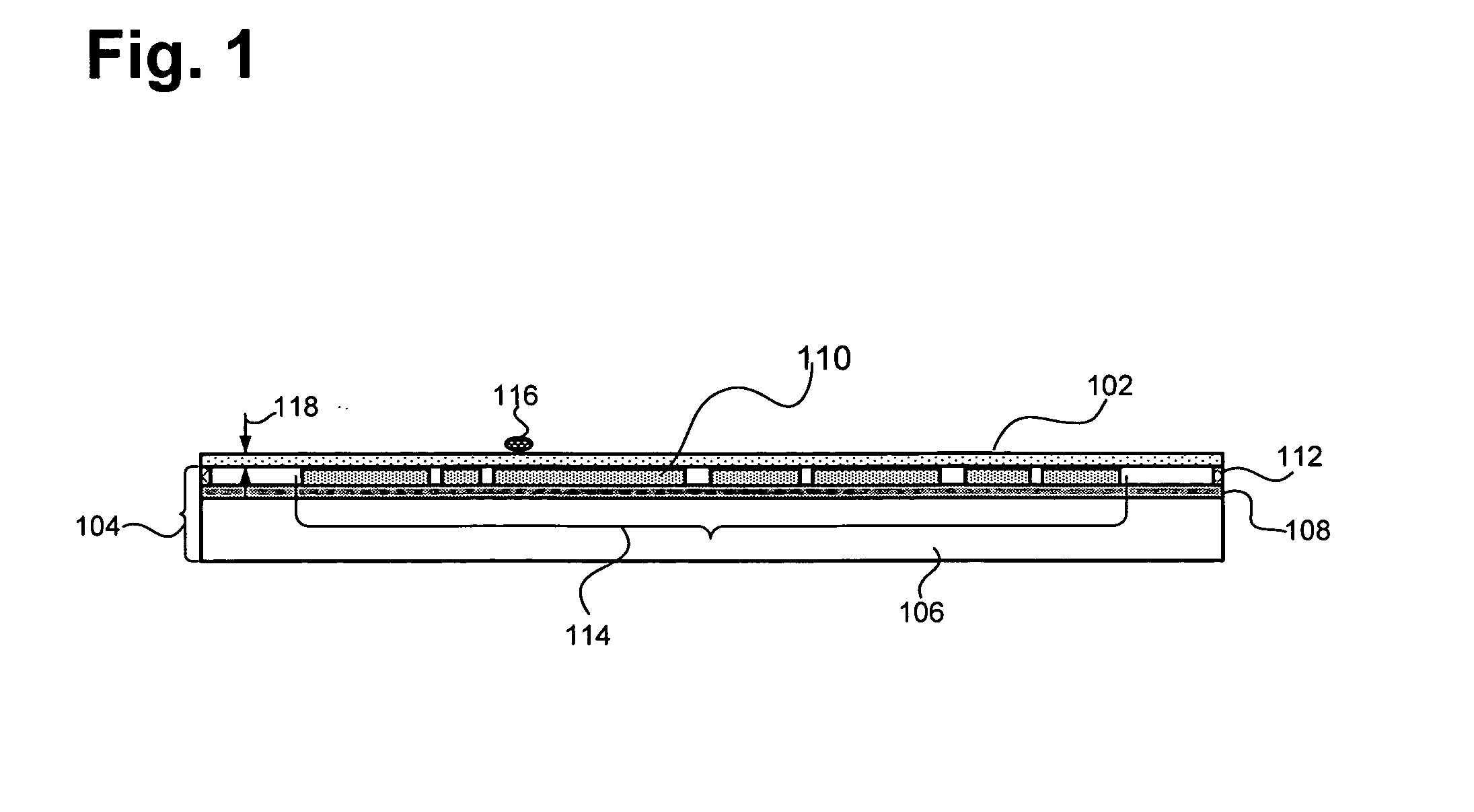
[0011]FIG. 1 shows an embodiment of the invention's carbon nanotube EUV pellicle 102 attached to an exemplary EUV lithographic mask 104 (also referred...


PUM

PropertyMeasurementUnit
thicknessaaaaaaaaaa
thicknessaaaaaaaaaa
thicknessaaaaaaaaaa

Abstract

According to one exemplary embodiment, an extreme ultraviolet (EUV) pellicle for use with a lithographic mask comprises a carbon nanotube film. The carbon nanotube EUV pellicle can be mounted on the lithographic mask. The carbon nanotube EUV pellicle protects the lithographic mask from contamination by undesirable particles and also prevents the undesirable particles from forming a focused image on the surface of a semiconductor wafer during fabrication; while advantageously, the carbon nanotube pellicle has a high level of EUV light transmittance.

Description

1. TECHNICAL FIELD[0001]The present invention is generally in the field of fabrication of semiconductor devices. More particularly, the invention is in the field of lithographic patterning of semiconductor wafers.2. BACKGROUND ART[0002]During semiconductor wafer fabrication, extreme ultraviolet (EUV) light can be utilized in a lithographic process to enable transfer of very small patterns, such as nanometer-scale patterns, from a mask to a semiconductor wafer. In EUV lithography, a pattern formed on an EUV lithographic mask (also referred to as an EUV reticle in the present application) can be transferred to a semiconductor wafer by reflecting EUV light off of portions of a reflective surface. A pellicle can be placed in front of the mask to, for example, avoid contamination of the mask and to prevent unwanted particles from reaching the mask surface, so as to avoid alteration of the pattern to be transferred by the mask.[0003]Due to the very short wavelengths (high frequencies) use...

Claims


Application Information

Patent Timeline
Patent Type & Authority Applications(United States)
IPC IPC(8): G03F1/00B32B3/00H01L21/50
CPCB82Y10/00B82Y40/00Y10T428/24802G03F1/62G03F7/70983G03F1/24
Inventor OKOROANYANWU, UZODINMAKIM, RYOUNG-HAN
Owner GLOBALFOUNDRIES US INC
Learn More