
Active vibratory noise control apparatus

a technology of vibratory noise and control apparatus, which is applied in the direction of active noise control, instruments, electrical transducers, etc., can solve the problems of high cost and complex configuration of the active vibratory noise control apparatus, and achieve the effect of reducing vibratory noise and simple arrangemen

Active Publication Date: 2008-06-26
HONDA MOTOR CO LTD +1
View PDF15 Cites 26 Cited by
  • Summary
  • Abstract
  • Description
  • Claims
  • Application Information

AI Technical Summary

Benefits of technology

[0008]It is an object of the present invention to provide an active vibratory noise control apparatus, which has a simple arrangement that is capable of reducing vibratory noise, regardless of changes in frequency of the vibratory noise.
[0009]Another object of the present invention is to provide an active vibratory noise control apparatus, which is reduced in cost and is capable of reducing vibratory noise within a wide space.
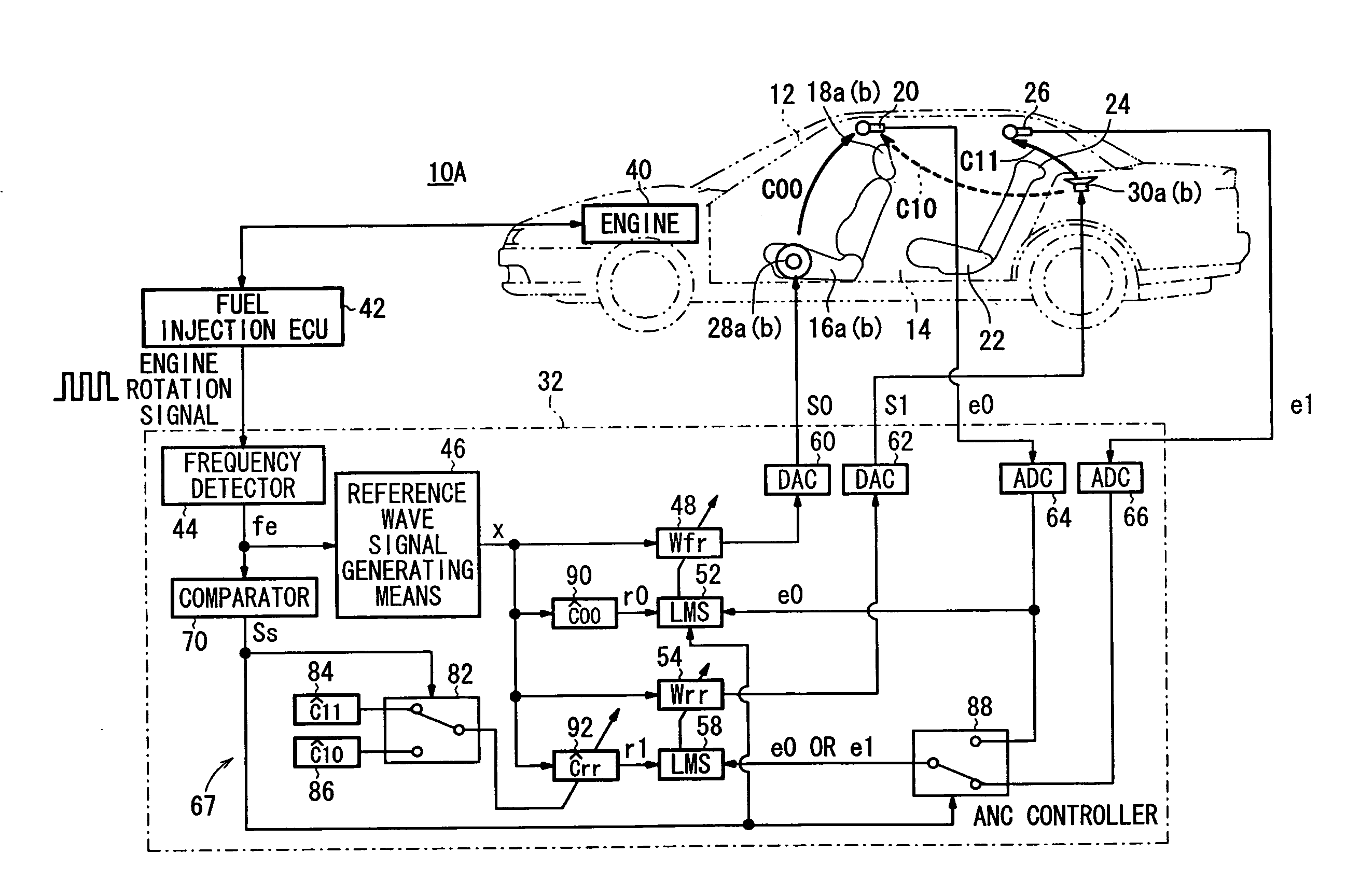
[0010]According to the present invention, an active vibratory noise control apparatus basically comprises a reference wave signal generator for generating a reference wave signal having a frequency based on the frequency of vibratory noise generated by a vibratory noise source, an adaptive filter for outputting a control signal based on the reference wave signal in order to cancel the vibratory noise, vibratory noise canceller for outputting vibratory noise canceling sounds based on the control signal, error signal detector for outputting an error signal based on the difference between the vibratory noise and the vibratory noise canceling sounds, corrector for correcting the reference wave signal and outputting a corrected reference wave signal as a reference signal to the error signal detector, based on a corrective value corresponding to signal transfer characteristics from the vibratory noise canceller, and filter coefficient updater for sequentially updating a filter coefficient of the adaptive filter in order to minimize the error signal based on the error signal and the reference signal.

Problems solved by technology

However, since the phase shifter is added to the apparatus for reducing noise in the passenger compartment, and the opposite phase signal is rotated in phase by means of the phase shifter, the active vibratory noise control apparatus has a complex configuration and is high in cost.

Method used


Image

  • Active vibratory noise control apparatus
  • Active vibratory noise control apparatus
  • Active vibratory noise control apparatus

Examples


first embodiment

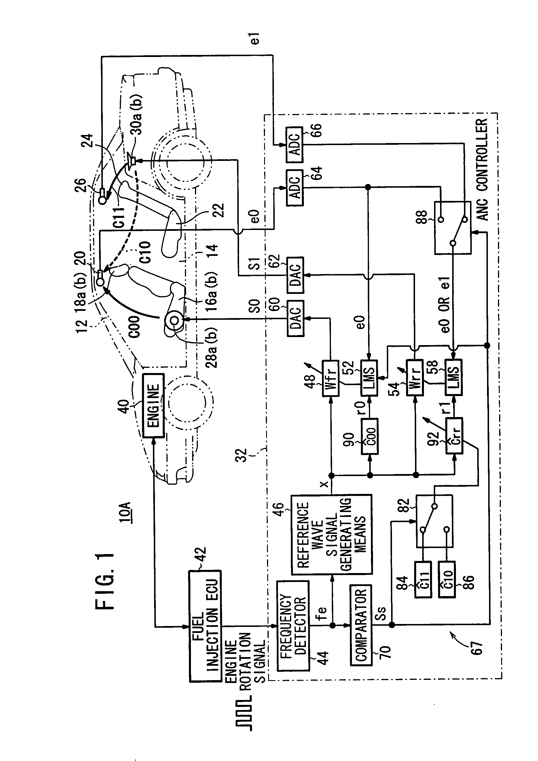
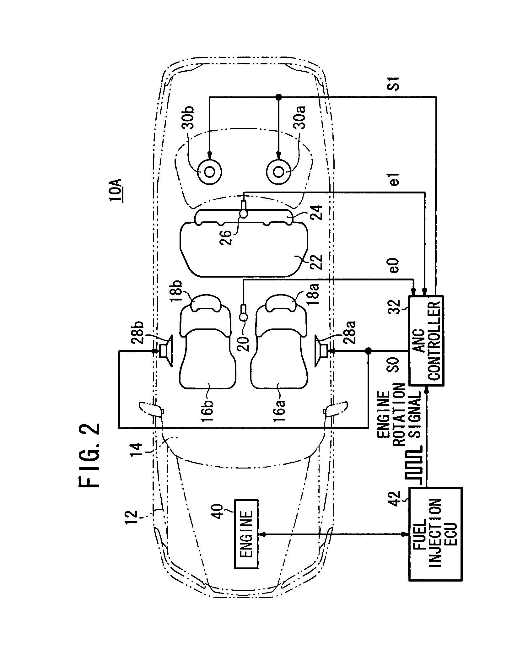
[0034]FIGS. 1 through 4 show an active vibratory noise control apparatus (hereinafter referred to as “ANC”) 10A according to the present invention, which is applied to reduce vibratory noise within a passenger compartment (space) 14 of a vehicle 12.

[0035]As shown in FIGS. 1 through 3, the ANC 10A includes a microphone (first error signal detector) 20 disposed on a roof lining near headrests 18a, 18b, i.e., near to an ear of a passenger (not shown), centrally over the front seats 16a, 16b in the passenger compartment 14, and another microphone (second error signal detecting means, second error signal detector) 26 disposed on a roof lining near a headrest 24, centrally over a rear seat 22 inside the passenger compartment 14.

[0036]The ANC 10A also includes a speaker 28a mounted on a left door near to the front seats 16a, 16b, a speaker 28b mounted on a right door near to the front seats 16a, 16b, and two speakers 30a, 30b disposed behind the rear seat 22. Alternatively, as shown in FIG...

third embodiment

[0067]An ANC 10C according to the present invention will be described below with reference to FIG. 6.

[0068]The ANC 10C is different from the ANCs 10A, 10B according to the first and second embodiments (see FIGS. 1 through 5) in that when the frequency fe reaches 140 Hz, the comparator 70 outputs a switching control signal Ss to the selectors 72, 78, 82, 88 and the filter coefficient updating means 52, 58.

[0069]The ANC 10C according to the third embodiment offers the same advantages as those of the switching means 67 of the ANCs 10A, 10B according to the first and second embodiments. In particular, the ANC 10C can reliably reduce engine noise within both the first and second spaces, near the front seats 16a, 16b and the rear seat 22 inside the passenger compartment 14, even when the frequency fe changes.

fourth embodiment

[0070]An ANC 10D according to the present invention will be described below with reference to FIG. 7.

[0071]The ANC 10D differs from the ANC 10B according to the second embodiment (see FIG. 5) in that only one microphone, i.e., the microphone 20, is disposed in the passenger compartment 14. Further, a selector 96 connects the memory 74 or the memory 86 to the correcting means 50 in response to the switching control signal Ss, and a selector (control signal supply switcher) 98 connects the DAC 60 or the DAC 62 to the adaptive filter 48 in response to the switching control signal Ss. The ANC controller 32 is free of the adaptive filter 54, the correcting means 56, the filter coefficient updating means 58, the selector 78, and the ADC 66. The ANC 10D also differs from the ANC 10B in that the first space is defined as a space near the front seats 16a, 16b within the passenger compartment 14, whereas the second space is defined as a space near the rear seat 22 within the passenger compart...


PUM


Abstract

When the frequency of an engine rotation signal reaches a predetermined frequency, a comparator of a switching unit outputs a switching control signal to selectors and a filter coefficient updater. Based on the switching control signal, the selector switches from a connection between one memory and a corrector to a connection between another memory and the corrector, thereby changing the transfer characteristics Ĉrr of the corrector from Ĉ11 to Ĉ10. Based on the switching control signal, the selector switches from a connection between one ADC and a filter coefficient updater to the connection between another ADC and the filter coefficient updater, thereby supplying the filter coefficient updater with an error signal, rather than an error signal.

Description

BACKGROUND OF THE INVENTION[0001]1. Field of the Invention[0002]The present invention relates to an active vibratory noise control apparatus for canceling vibratory noises produced by a vibratory noise source by means of vibratory noise canceling sounds that are opposite in phase to the vibratory noise, and more particularly to an active vibratory noise control apparatus for reducing vibratory noises produced within a passenger compartment of a vehicle by a vibratory noise source such as the vehicle engine.[0003]2. Description of the Related Art[0004]Conventional active vibratory noise control apparatus operate by detecting noise in the passenger compartment of a vehicle by means of a microphone disposed centrally over the front seats near the position of an ear of a passenger, then generating a signal that is opposite in phase to an output signal produced by the microphone based on the noise, and outputting canceling sounds based on the generated signal into the passenger compartme...

Claims


Application Information

Patent Timeline
Patent Type & Authority Applications(United States)
IPC IPC(8): G10K11/16
CPCG10K11/1786G10K2210/3046G10K2210/1282G10K11/17823G10K11/1783G10K11/17854G10K11/17857G10K11/17883
Inventor SAKAMOTO, KOSUKEINOUE, TOSHIOTAKAHASHI, AKIRAKOBAYASHI, YASUNORIYAMAGATA, KENJIFUKUMOTO, SHINJI
Owner HONDA MOTOR CO LTD
Learn More