
Liquid crystal display device

a liquid crystal display and display device technology, applied in static indicating devices, non-linear optics, instruments, etc., can solve the problems of ocb liquid crystal display devices being prone to influence, more time is taken, and transition takes longer time, so as to achieve the effect of keeping power consumption low

Inactive Publication Date: 2008-06-19
TOSHIBA MATSUSHITA DISPLAY TECH
View PDF14 Cites 0 Cited by
  • Summary
  • Abstract
  • Description
  • Claims
  • Application Information

AI Technical Summary

Benefits of technology

[0008]The present invention has been made in view of the above problems, and an object of the invention is therefore to provide a liquid crystal display device which can display an image quickly even when switching is made from a standby state to a display state and can maintain a standby state with a low power consumption.
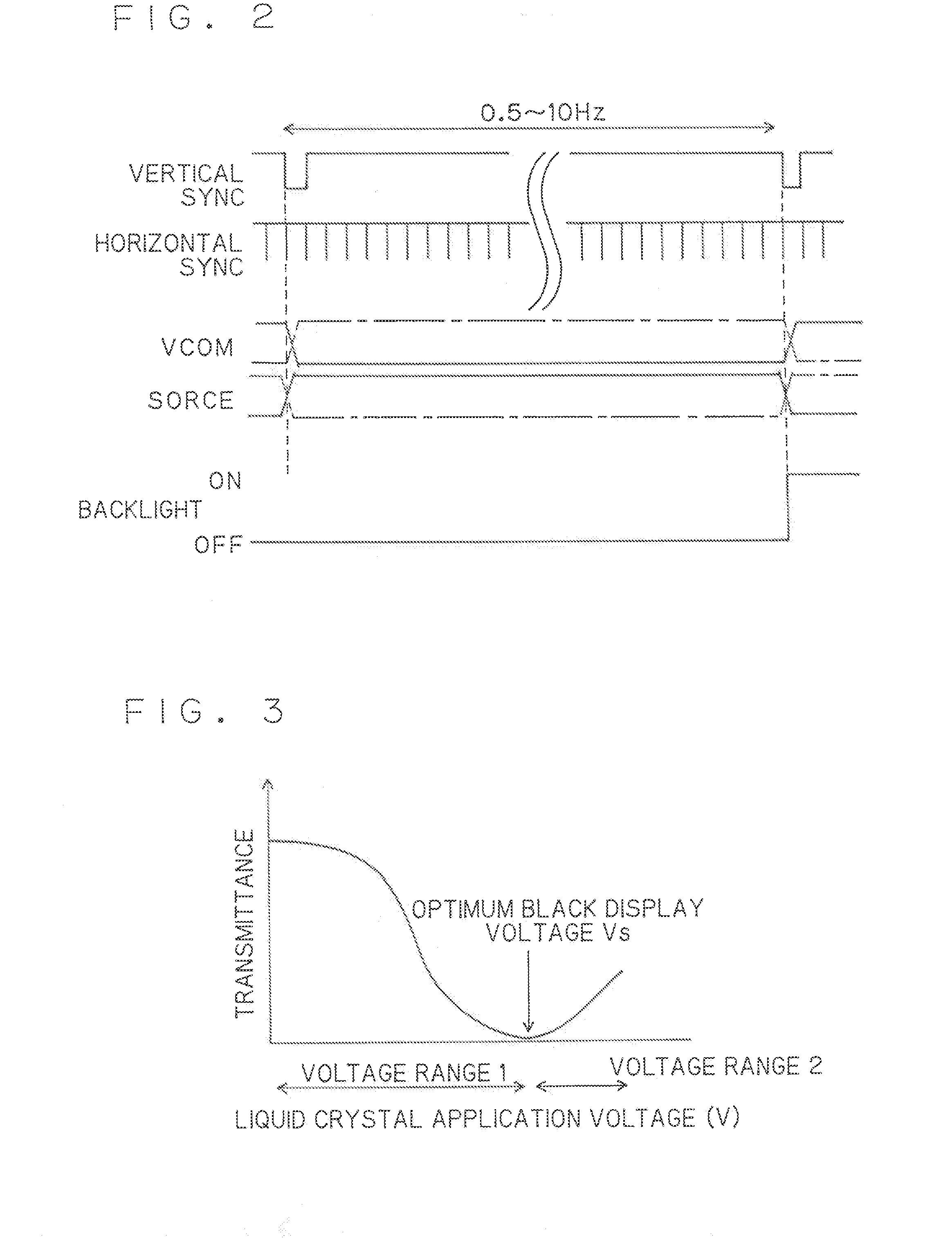
[0010]According to the invention, since the AC voltage which is applied to the OCB liquid crystal is higher than or equal to the reverse transition prevention voltage, a display state can be established quickly from a standby state. Furthermore, since the frame frequency is lower than in the image display state, the power consumption can be kept low in the standby state.

Problems solved by technology

However, OCB liquid crystal display devices are different from such ordinary liquid crystal display devices in that, first, it is necessary to cause a transition from spray alignment to bend alignment, that is, to cause an initial transition by applying a high voltage to the OCB liquid crystal, before establishing a display state.
This means a problem that because of the initial transition, more time is taken until an image appears on the liquid crystal display device.
In particular, OCB liquid crystal display devices are prone to be influenced by temperature, and there is another problem that this transition takes longer time as the environment temperature lowers.

Method used


Image

  • Liquid crystal display device
  • Liquid crystal display device
  • Liquid crystal display device

Examples


Embodiment Construction

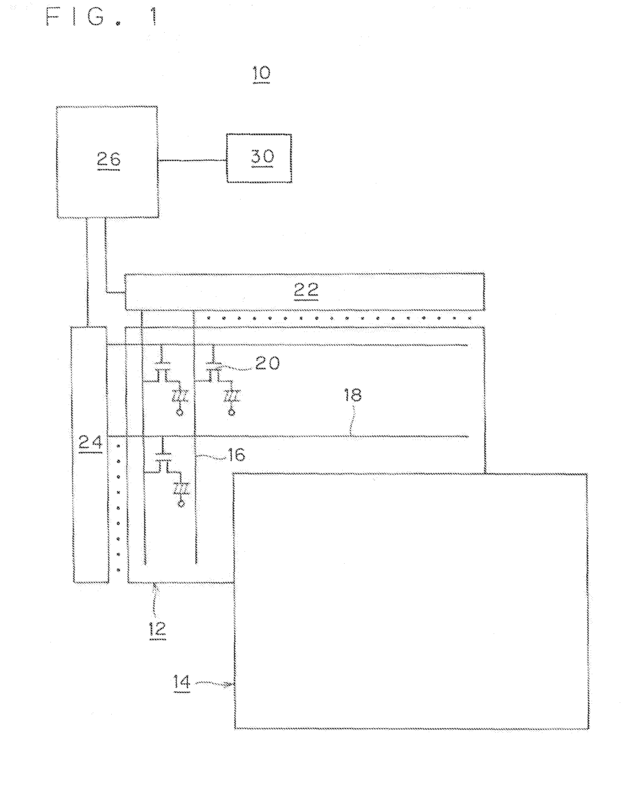
[0014]An OCB liquid crystal display device 10 according to an embodiment of the present invention will be hereinafter described with reference to FIGS. 1 and 2. For example, the liquid crystal display device 10 is a 3-inch WQVGA (240×RGB×400) liquid crystal display device used in a cell phone.

(1) Configuration of Liquid Crystal Display Device 10

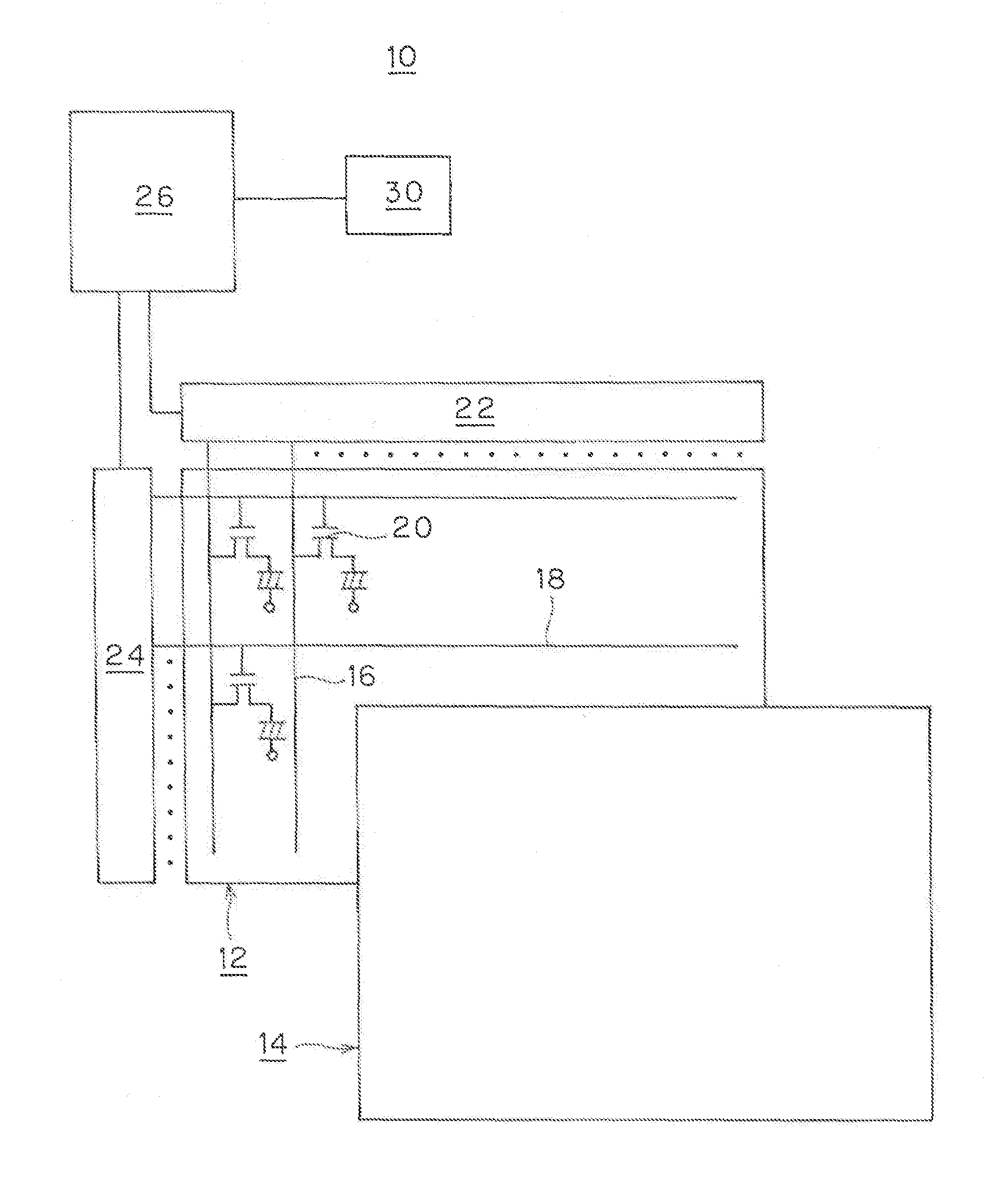
[0015]The configuration of the liquid crystal display device 10 will be described with reference to FIG. 1. The liquid crystal display device 10 is equipped with an array substrate 12, a counter substrate 14, and a liquid crystal (OCB liquid crystal) which is held between the substrates 12 and 14.

[0016]In the array substrate 12, plural signal lines 16 and plural scanning lines 18 are arranged perpendicularly to each other on a glass substrate and thin-film transistors (hereinafter abbreviated as TFTs) 20 are formed in matrix form in the vicinities of the respective crossing positions of the signal lines 16 and the scanning lines 18.

[0017]The ...


PUM


Abstract

In a liquid crystal display device having an OCB liquid crystal panel, the frame frequency is set at 0.5 to 10 Hz and a reverse transition prevention voltage is set at 1 V while the liquid crystal panel is in a standby state.

Description

FIELD OF THE INVENTION[0001]The present invention relates to an OCB (optically compensated birefringence) liquid crystal display device.BACKGROUND OF THE INVENTION[0002]Conventionally, TN liquid crystal display devices have been used most commonly. However, recently, to improve the visibility of moving images, OCB liquid crystal display devices which are characterized in high response speeds have come to be incorporated in liquid crystal TV receivers, liquid crystal monitors, etc. (refer to Japanese Patent Application Kokai No. 2004-185027, for example).[0003]OCB liquid crystal display devices perform display utilizing birefringence and hence can perform black display only at a particular voltage. As shown in FIG. 3, the transmittance increases and gradation inversion occurs in a voltage range 2 which is higher than the above optimum black display voltage. Therefore, in OCB liquid crystal display devices, the black display voltage V is set at the optimum black display voltage Vs (lu...

Claims


Application Information

Patent Timeline
IPC IPC(8): G02F1/133
CPCG09G3/3614G09G2320/0252G09G2310/06G09G3/3648
Inventor MAEDA, TOMOYUKI
Owner TOSHIBA MATSUSHITA DISPLAY TECH
Learn More