
Sensors, methods and systems for determining physical effects of a fluid

Inactive Publication Date: 2008-06-19
LUNA INNOVATIONS
View PDF6 Cites 69 Cited by
  • Summary
  • Abstract
  • Description
  • Claims
  • Application Information

AI Technical Summary

Benefits of technology

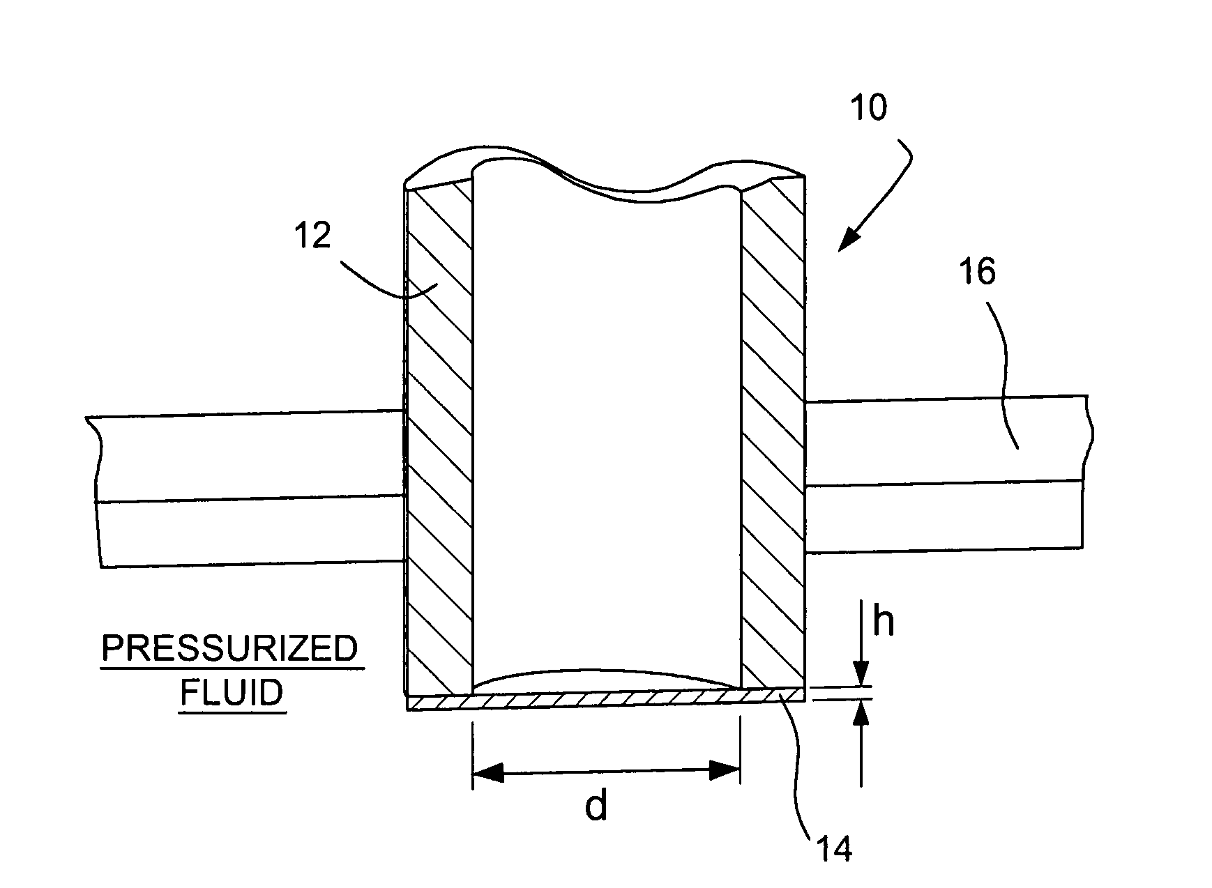
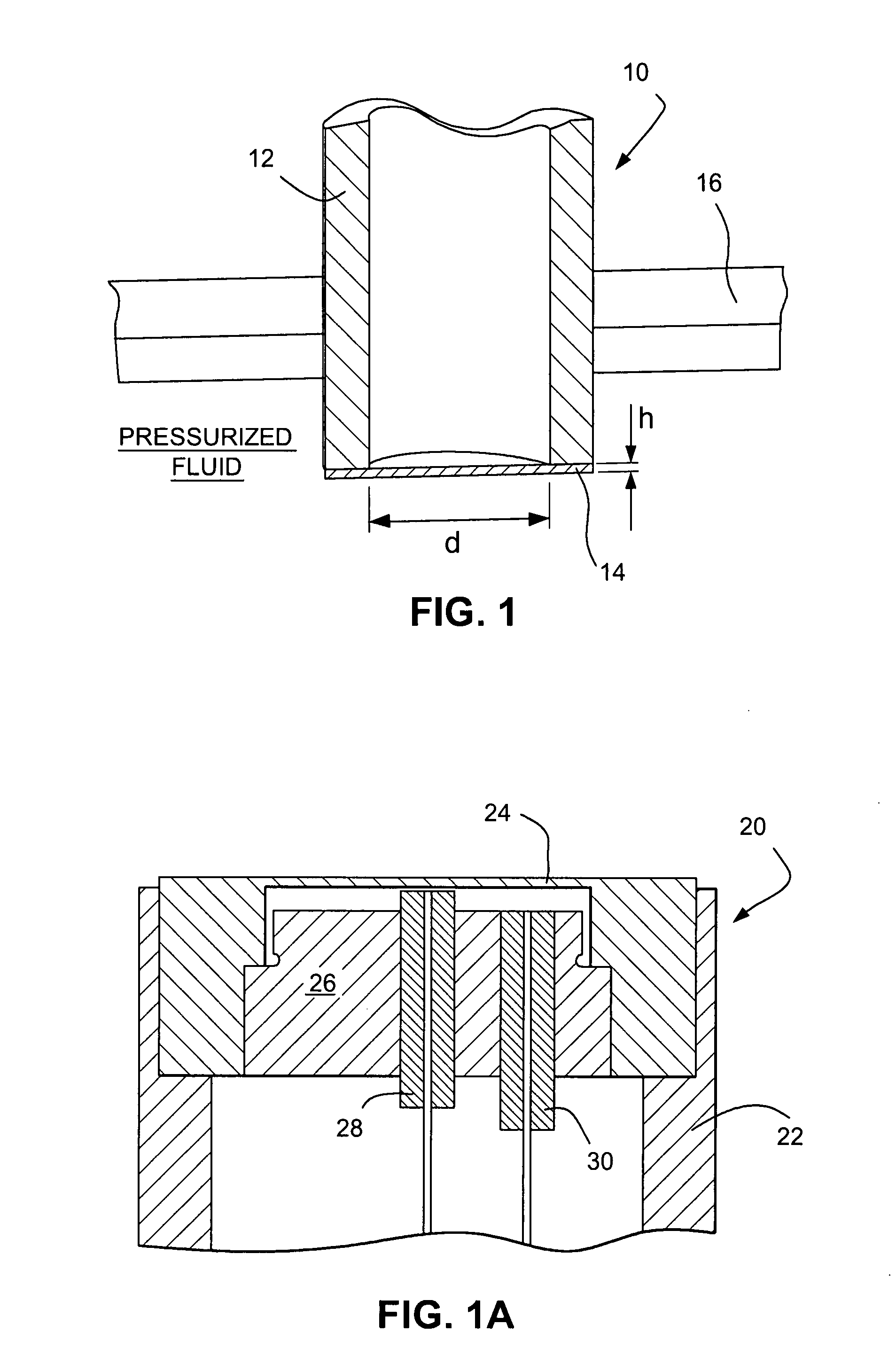
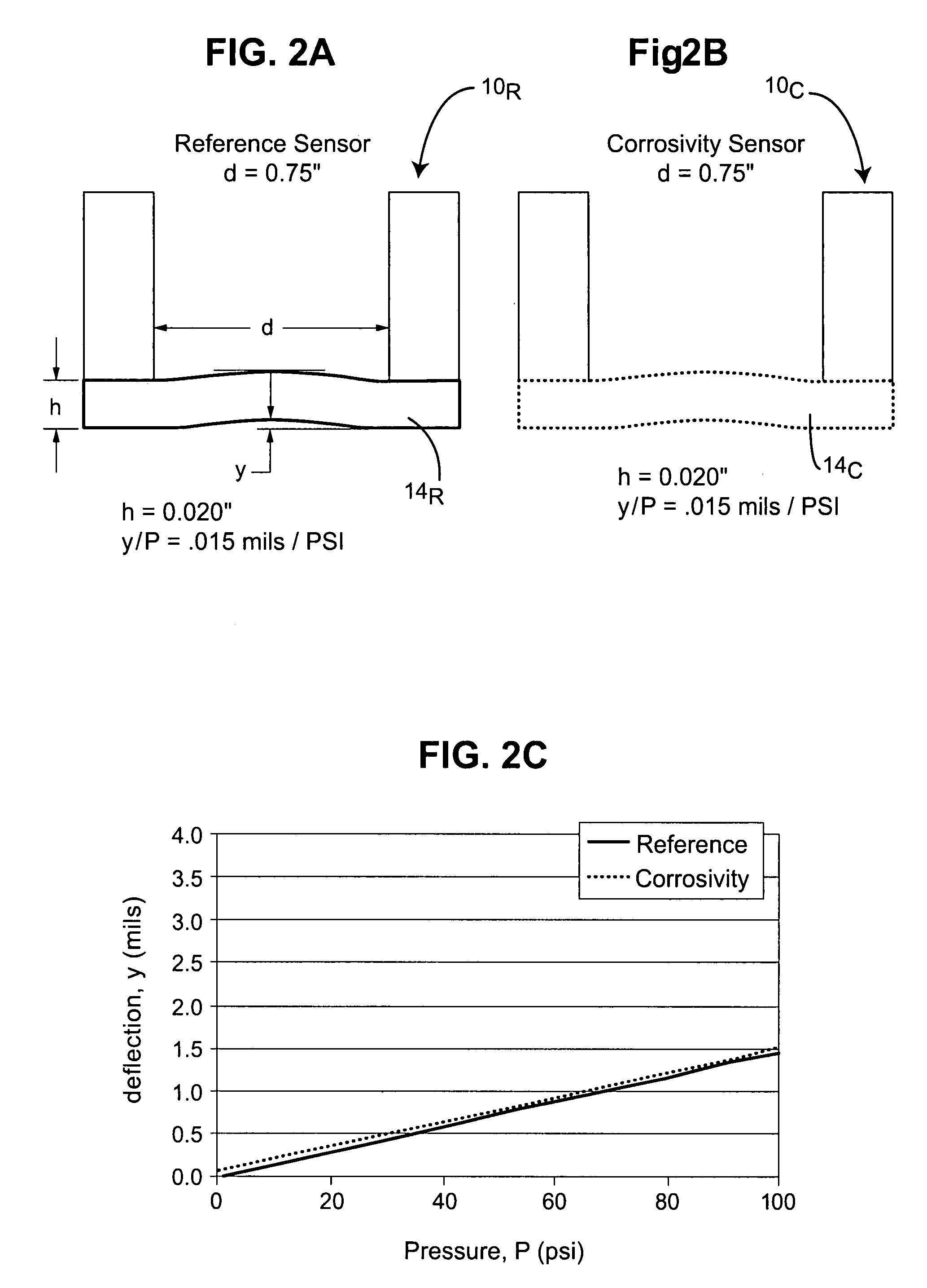
[0014]By way of example, if fluid corrosion is being monitored, then such corrosion causes the diaphragm to thin which consequently alters the mechanical response (e.g., deflection, strain or resonant frequency characteristics) of the diaphragm relative to a non-corroding reference sensor or some baseline condition. Detection of the change in the mechanical response of the diaphragm when actuated (e.g., by means of the fluid pressure in contact with the sensor) will thus enable measurement of corrosion rate and cumulative corrosion damage.

Problems solved by technology

By way of example, if fluid corrosion is being monitored, then such corrosion causes the diaphragm to thin which consequently alters the mechanical response (e.g., deflection, strain or resonant frequency characteristics) of the diaphragm relative to a non-corroding reference sensor or some baseline condition.

Method used


Image

  • Sensors, methods and systems for determining physical effects of a fluid
  • Sensors, methods and systems for determining physical effects of a fluid
  • Sensors, methods and systems for determining physical effects of a fluid

Examples


examples

[0058]The results of testing in flow cells clearly demonstrated the functionality of the herein disclosed physical effects sensors for monitoring corrosivity of flowing water systems. Through this testing, the following significant attributes have been demonstrated:[0059]Sensors integrated into corporation stops and evaluated under representative conditions for water systems,[0060]Repeatable measurement of mechanical response in pressurized fluid,[0061]Using a reference sensor the mechanical response sensitivity was independent of other environmental factors such as temperature,[0062]Mechanical response sensitivity measured using optical fiber sensors was a strong function of the cumulative corrosion of the diaphragm, and[0063]One to one relationship and excellent correlation (R2>0.99) between the electrochemical Faraday's Law calculations and the measured thickness based on a mechanics model of the physical effects sensor response.

[0064]Non-Corrosion Environmental Compensation Test...


PUM

PropertyMeasurementUnit
pressureaaaaaaaaaa
thicknessaaaaaaaaaa
pressureaaaaaaaaaa

Abstract

Sensors, methods and systems detect physical effects (e.g., corrosion, erosion, scaling and / or oxidation) of a fluid in contact with a diaphragm associated with a sensor assembly. The diaphragm preferably exhibits a first mechanical response when initially placed into contact with a fluid and a second mechanical response different from the first mechanical response after exposure to the fluid for a predetermined period of time. A change in the diaphragm mechanical responses between at least the first and second mechanical responses is therefore indicative of physical effects on the diaphragm over time caused by the fluid in contact therewith. A mechanical response sensor is operatively associated with the diaphragm so as to measure the change in the diaphragm mechanical responses and thereby determine the physical effects over time of the fluid in contact with the diaphragm. In some embodiments, the diaphragm is actuated due to a pressure condition exerted by the fluid or in other embodiments the diaphragm is internally actuated. Internal actuation includes pneumatic, hydraulic or piezoelectric means for producing a mechanical response of the diaphragm. In one embodiment, therefore, fluid corrosivity may be sensed by bringing a sensor assembly having a pressure-actuated diaphragm into contact with a corrosive fluid, exerting a pressure condition on the diaphragm so as to cause the mechanical response of the diaphragm, measuring the diaphragm deflection or strain, and then deriving fluid corrosivity from the measured diaphragm mechanical response.

Description

CROSS REFERENCE TO RELATED APPLICATION[0001]This application is based on and claims domestic priority benefits under 35 USC §119(e) from U.S. Provisional Patent Application Ser. No. 60 / 861,981 filed on Dec. 1, 2006, the entire content of which is expressly incorporated hereinto by reference.GOVERNMENT RIGHTS STATEMENT[0002]This invention was made with Government support under Grant No. W9132T-06-C-0017 awarded by the U.S. Army. The Government has certain rights in the invention.FIELD OF INVENTION[0003]The present invention relates generally to the field of sensors. In especially preferred embodiments, the present invention relates to sensors, methods and systems that my usefully be employed to detect the physical effects of a fluid (e.g., liquid, gas and multiphase media such as liquid slurries with suspended particulates) over time, such as the effects of corrosion, erosion, scaling and / or oxidation caused by the fluid. These detected physical effects of the fluid may then be used ...

Claims


Application Information

Patent Timeline
Patent Type & Authority Applications(United States)
IPC IPC(8): G01L9/00
CPCG01N17/04
Inventor WAVERING, THOMAS A.FRIEDERSDORF, FRITZ J.BROWN, NATHAN K.
Owner LUNA INNOVATIONS
Learn More