Eureka AIR delivers breakthrough ideas for toughest innovation challenges, trusted by R&D personnel around the world.

Elevator installation, a guide rail of an elevator installation, brake equipment of an elevator installation and a method for guiding, holding and braking an elevator installation

a technology for braking equipment and elevators, which is applied in the direction of track-braking member co-operation, liftators, transportation and packaging, etc., can solve the problems of high construction space and high cost, and achieve the effects of increasing friction, good chemical and mechanical properties, and high comfort demands

Inactive Publication Date: 2008-06-12
INVENTIO AG
View PDF16 Cites 21 Cited by
  • Summary
  • Abstract
  • Description
  • Claims
  • Application Information

AI Technical Summary

Benefits of technology

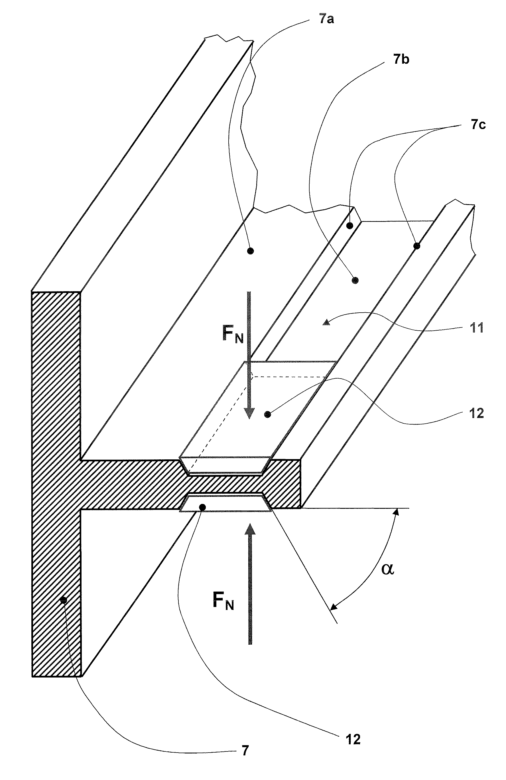
[0016]A pressing device for holding and braking the car can be designed, in correspondence with the wedge angle α, with lower pressing forces FN. This enables use of smaller drive units or brake release units, which is correspondingly more favorable.
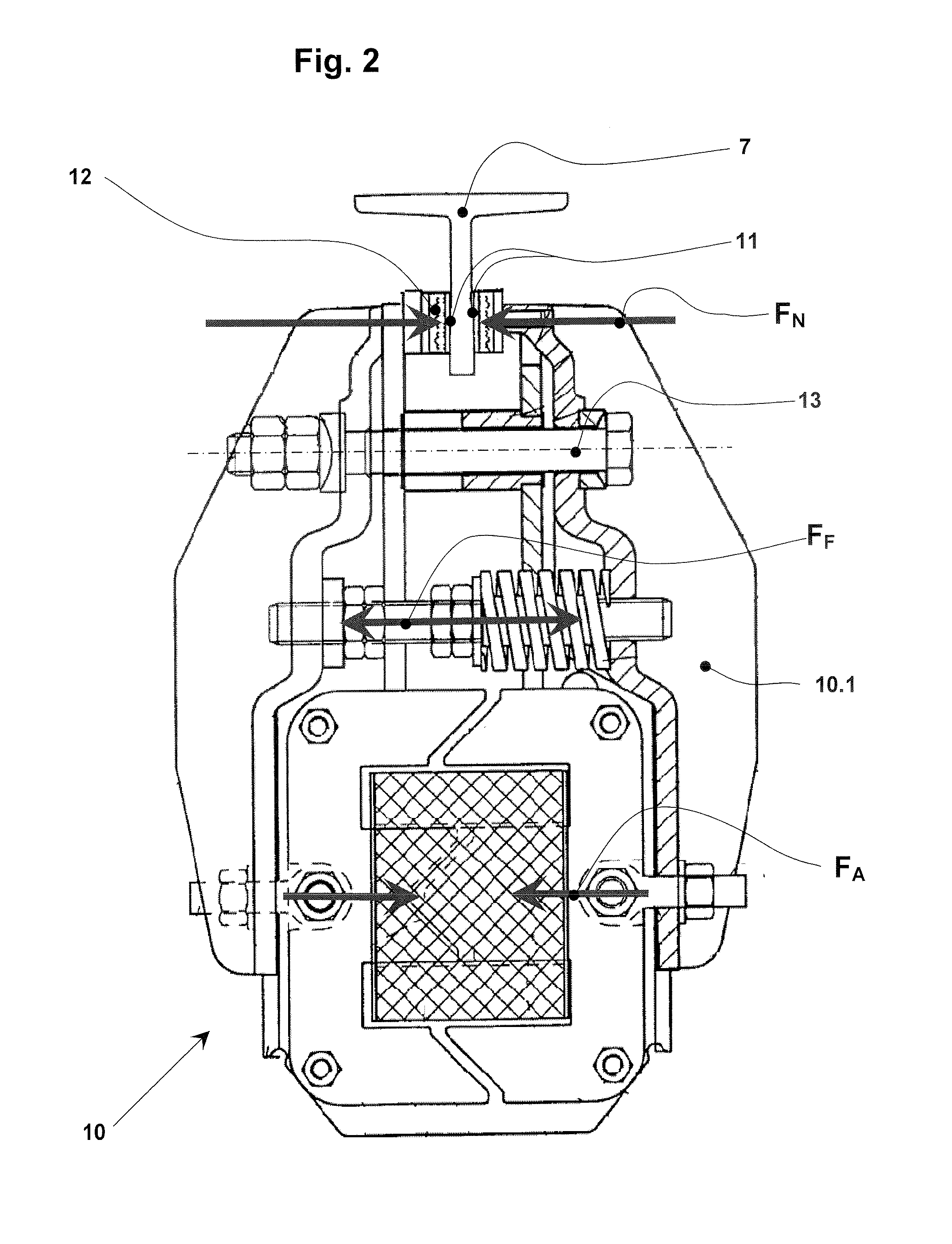
[0026]In an alternative embodiment the brake equipment is arranged in the region of a drive motor and the brake surface is disposed in direct connection with a drive pulley or a drive shaft of the drive motor. In this connection the braking and holding action of the brake equipment is transmitted to the elevator car by way of supporting and drive means. A holding brake in the drive can thereby be provided economically, since as a consequence of the wedge action a reduced braking force is possible.

Problems solved by technology

The problem with this solution is now to be seen in the fact that the brake equipment has to include sliding equipment so as to make possible, in the case of braking, a gentle stopping of the elevator car.
This necessitates much constructional space and is expensive.

Method used


Image

  • Elevator installation, a guide rail of an elevator installation, brake equipment of an elevator installation and a method for guiding, holding and braking an elevator installation
  • Elevator installation, a guide rail of an elevator installation, brake equipment of an elevator installation and a method for guiding, holding and braking an elevator installation
  • Elevator installation, a guide rail of an elevator installation, brake equipment of an elevator installation and a method for guiding, holding and braking an elevator installation

Examples


Embodiment Construction

[0033]The following detailed description and appended drawings describe and illustrate various exemplary embodiments of the invention. The description and drawings serve to enable one skilled in the art to make and use the invention, and are not intended to limit the scope of the invention in any manner. In respect of the methods disclosed, the steps presented are exemplary in nature, and thus, the order of the steps is not necessary or critical.

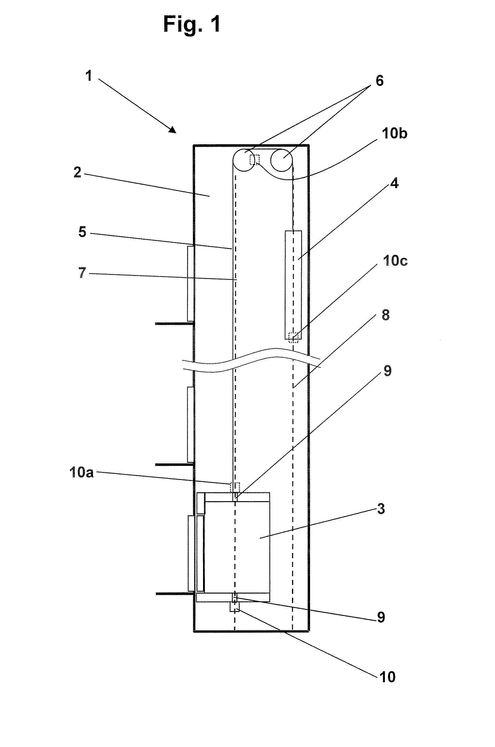
[0034]One possible overall arrangement of an elevator installation is illustrated in FIG. 1. The elevator installation 1 consists of an elevator car 3 for reception of goods or persons. The car is arranged to be movable along a guide path or by guide rails 7. The elevator installation 1 is installed in a shaft 2 of a building. The elevator car is connected with a counterweight 4 by way of supporting and drive means 5. The car 3 is moved in opposite sense to the counterweight 4 by means of a drive 6, which in the illustrated example acts on t...


PUM


Abstract

An elevator installation includes a guide rail and brake equipment for guiding, holding and braking the elevator installation. The brake equipment has a brake lining which co-operates with a brake surface, advantageously with the brake surface of the guide rail, for the purpose of the braking and holding. The brake surface has at least one longitudinal wedge groove or wedge elevation which is oriented in the braking direction and on which the brake lining acts in case of need. An amplification of the braking force is achieved by the longitudinal wedge groove or wedge elevation.

Description

FIELD OF THE INVENTION[0001]The present invention relates to an elevator installation, to a guide rail of an elevator installation, to brake equipment of an elevator installation and to a method for guiding, holding and braking an elevator installation.BACKGROUND OF THE INVENTION[0002]An elevator installation substantially serves for vertical transport of goods or persons. The elevator installation includes for this purpose an elevator car for reception of the goods or persons, which elevator car is movable along a guide path. As a rule, the elevator installation is installed in a building and the elevator car transports goods or persons from and to various floors of this building. In a customary construction the elevator car is installed in a shaft of the building and it contains, apart from the car, support means which connect the car with the counterweight. The elevator car is moved by means of a drive, which acts selectably on the support means or directly on the elevator car or...

Claims


Application Information

Patent Timeline
IPC IPC(8): B66B5/16B66B7/02
CPCB66B7/022B66B5/18B66B5/16B66B11/04B82Y30/00
Inventor KOCHER, HANSMUFF, JOSEF A.
Owner INVENTIO AG
Why Eureka
Eureka Blog
Learn More