
Interlocking solar roof tiles with heat exchange

Inactive Publication Date: 2008-06-12
NS ACQUISITION
View PDF89 Cites 43 Cited by
  • Summary
  • Abstract
  • Description
  • Claims
  • Application Information

AI Technical Summary

Benefits of technology

[0007]Described herein are various solar roof tiles that produce energy from the sun's radiation as well as various methods employed in fabrication of those solar tiles. Some of the tiles have increased efficiency in converting solar energy to electricity, are aesthetically attractive, and well suited for installation on unfinished rooftops. Some tiles minimize or prevent weather from reaching the underlying materials of a rooftop and together form a finished roof of a house. Some of the tiles are configured for attachment directly to battens or purlins for ease of installation.
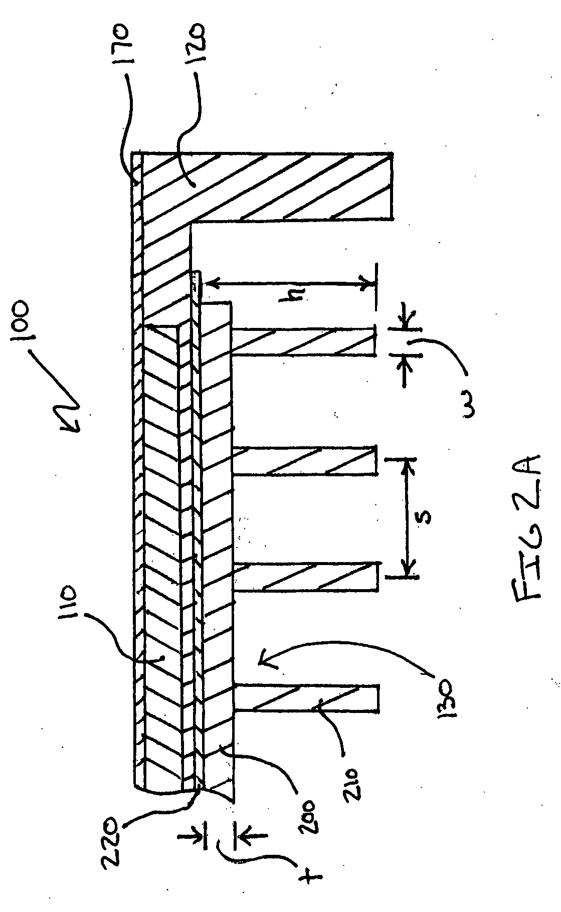
[0017]In another instance, each photovoltaic tile has a thermal interface layer between said heat sink and said unexposed surface to improve heat dissipation.

Problems solved by technology

Despite increased growth, the widespread use of conventional roof-mounted solar modules has been limited by their difficulty and cost of installation, lack of aesthetic appeal, and especially their low conversion efficiency.
These modules are complex systems comprising separate mechanical and electrical interconnections that are then mounted into existing rooftops, requiring significant installation time and skill.
Additionally, because existing modules do not provide weather protection to roof tops, homeowners are subjected to material and labor costs for both the modules and the protective roofing material to which they are mounted.
Modules are also invasive in the aesthetics of homes and commercial buildings, resulting in limited use.
A few manufacturers have fabricated more aesthetically pleasing and less obstructive solutions, but the systems are not price competitive largely due to installation difficulties and poor total area efficiency.
Lower module efficiency levels are correlated to higher photovoltaic system costs because a greater module area is required for a given energy demand.
Despite these improvements, solar cell conversion efficiency remains limited, in part, by high solar cell temperatures.
Part of the energy radiated onto the cell is converted to heat, which limits the electrical energy output and overall conversion efficiency of the cell.

Method used


Image

  • Interlocking solar roof tiles with heat exchange
  • Interlocking solar roof tiles with heat exchange
  • Interlocking solar roof tiles with heat exchange

Examples


Embodiment Construction

[0046]The following description is presented to enable a person of ordinary skill in the art to make and use the invention. Descriptions of specific materials, techniques, and applications are provided only as examples. Various modifications to the examples described herein will be readily apparent to those of ordinary skill in the art, and the general principles defined herein may be applied to other examples and applications without departing from the spirit and scope of the invention. Thus, the present invention is not intended to be limited to the examples described and shown, but is to be accorded the scope consistent with the appended claims.

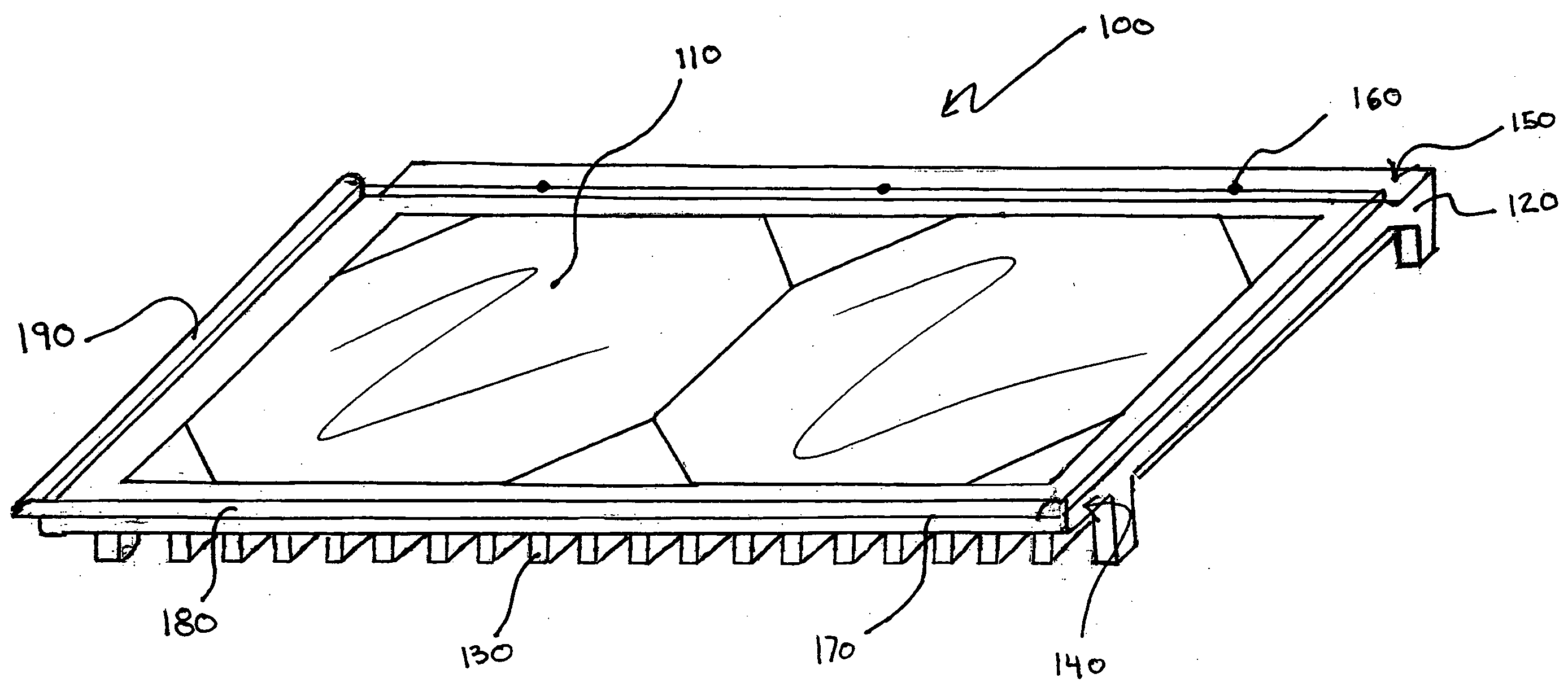
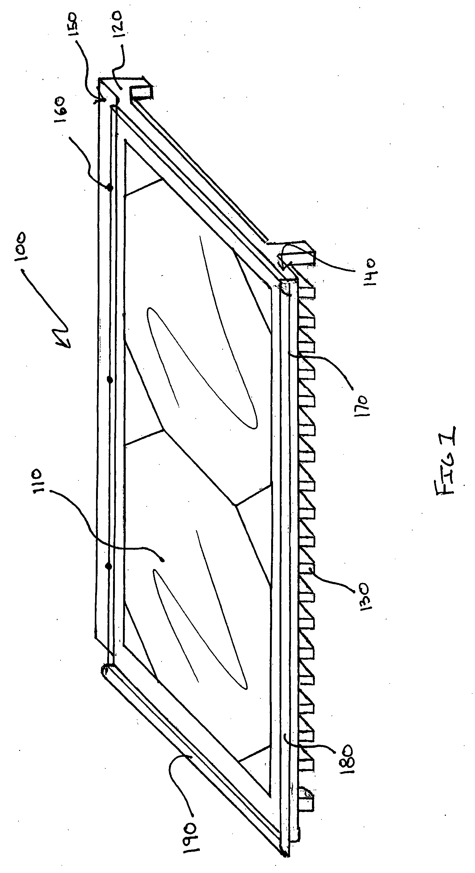
[0047]FIG. 1 illustrates an example of a photovoltaic (PV) tile 100 of the present invention. The photovoltaic tile 100 comprises one or more photovoltaic cells 110 positioned in a housing 120. The housing may lie on an unfinished roof surface horizontally with respect to the length of the roof. Each photovoltaic cell is positioned within ...


PUM

PropertyMeasurementUnit
Temperatureaaaaaaaaaa
Electrical conductoraaaaaaaaaa

Abstract

A photovoltaic tile with photovoltaic cell and a heat sink. The heat sink is attached on a side of the cell opposite to the light-receiving side of the photovoltaic cell and can remove heat caused by light absorbed by the photovoltaic cell but not converted to electricity as well as heat generated by electrical resistance. A photovoltaic tile formed of such cells can exhibit greater energy conversion efficiency as a result of the ability to dissipate the heat. The tiles can be arranged on a roof to protect the roof structure and generate electricity. Photovoltaic tiles comprising interlocking mechanical and electrical connections for ease of installation are described. Methods of making photovoltaic tiles involve e.g. laminating a heat sink to a photovoltaic cell and / or injection molding.

Description

CROSS REFERENCE TO RELATED APPLICATIONS[0001]This application claims priority benefit of U.S. Provisional Application No. 60 / 874,313, entitled “Modular Solar Roof Tiles And Solar Panels With Heat Exchange” filed Dec. 11, 2006, which is incorporated by reference in its entirety herein as if it was put forth in full below.BACKGROUND OF THE INVENTION[0002]Solar energy is a renewable energy source that has gained significant worldwide popularity due to the recognized limitations of fossil fuels and safety concerns of nuclear fuels. The photovoltaic (PV) solar energy demand has grown at least 25% per annum over the past 15 years. Worldwide photovoltaic installations increased by 1460 MW (Megawatt) in 2005, up from 1,086 MW installed during the previous year (representing a 34% yearly increase) and compared to 21 MW in 1985.[0003]Growth in the field of solar energy has focused on solar modules fixed on top of an existing roof. Rooftops provide direct exposure of solar radiation to a solar...

Claims


Application Information

Patent Timeline
IPC IPC(8): H01L31/024H01L31/0203
CPCH01L31/052Y02B10/12H02S20/25Y02E10/50Y02B10/20B29C45/14639B29C45/1671H01M14/005H02S20/23H02S40/36H02S40/42Y02B10/10Y10T29/49112Y10T29/49114H01L31/0203H01L31/024
Inventor CORRALES, EUGENIA M.
Owner NS ACQUISITION
Learn More