
Method of manufacturing semiconductor device

a manufacturing method and semiconductor technology, applied in semiconductor/solid-state device manufacturing, basic electric elements, electric devices, etc., can solve the problems of affecting the operation speed of lsi circuits, affecting the reliability and yield of products, and affecting the signal transmission speed of interconnects, etc., to achieve simple structure and satisfying electrical characteristics

Inactive Publication Date: 2008-06-05
NEC ELECTRONICS CORP
View PDF4 Cites 3 Cited by
  • Summary
  • Abstract
  • Description
  • Claims
  • Application Information

AI Technical Summary

Benefits of technology

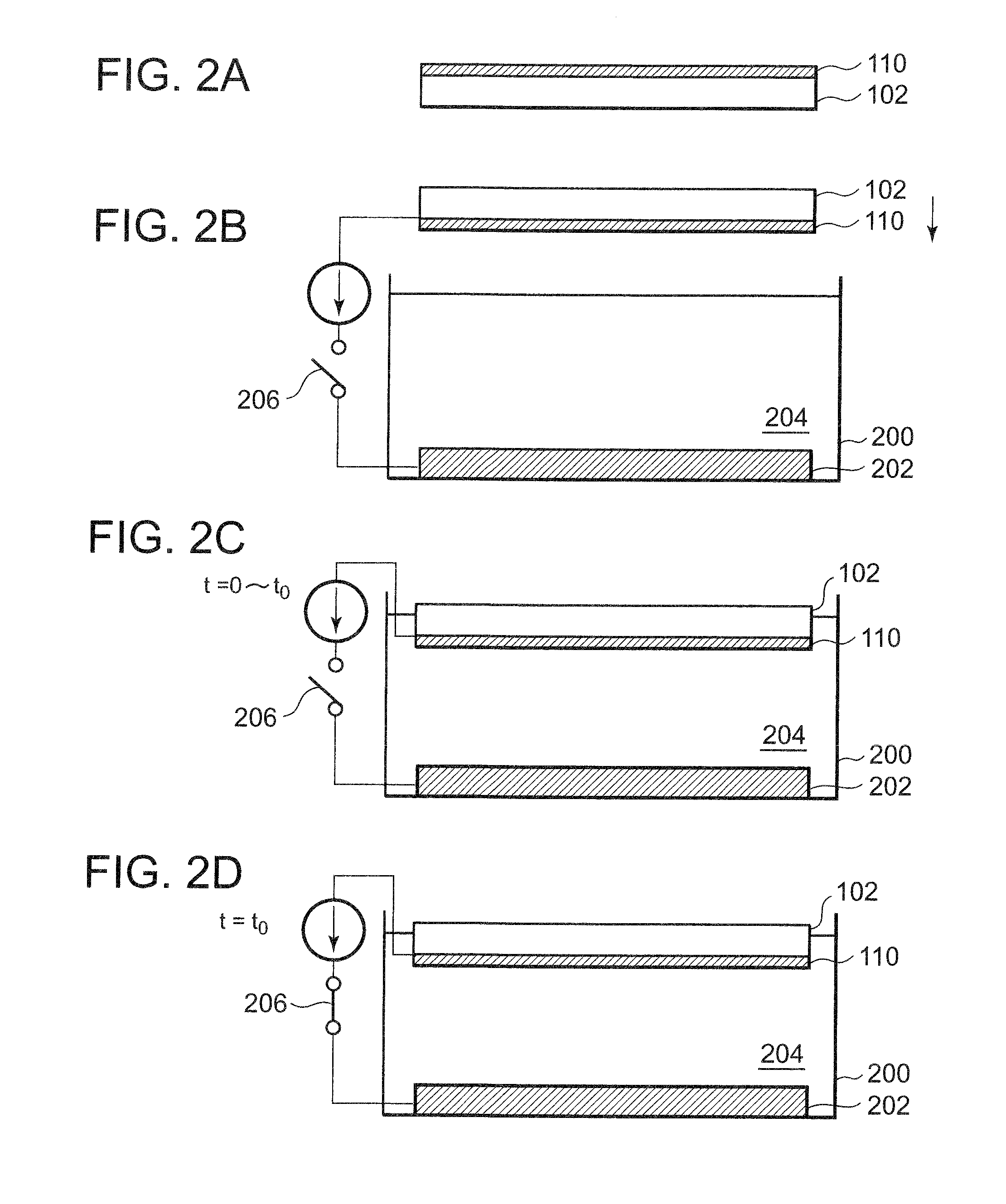
[0020]According to the present invention, because, in immersion, no voltage is applied between the barrier metal film and the anode and the barrier metal film and the anode are substantially at the same potential, abnormal growth can be prevented. Further, because the semiconductor substrate is immersed in the plating solution for the predetermined length of time with the barrier metal film and the anode being substantially at the same potential, gases such as air are removed during the predetermined length of time, and thus, a uniform plating film can be obtained even if the substrate is not immersed obliquely.
[0023]According to the present invention, a copper film having satisfactory electrical characteristics with a simple structure can be obtained.

Problems solved by technology

In recent semiconductor devices, delay in signal transmission on interconnects may sometimes determine operation speed of LSI circuits.
When there is a void in copper interconnect, there arises problems such as an increase in resistance of the copper interconnect, and decreases in reliability and yield of products.
Such pretreatment is carried out in a bath or an apparatus that is different from a plating bath containing the plating solution, which makes the plating apparatus larger or more complicated and decreases the throughput at the plating step.

Method used


Image

  • Method of manufacturing semiconductor device
  • Method of manufacturing semiconductor device
  • Method of manufacturing semiconductor device

Examples


example 1

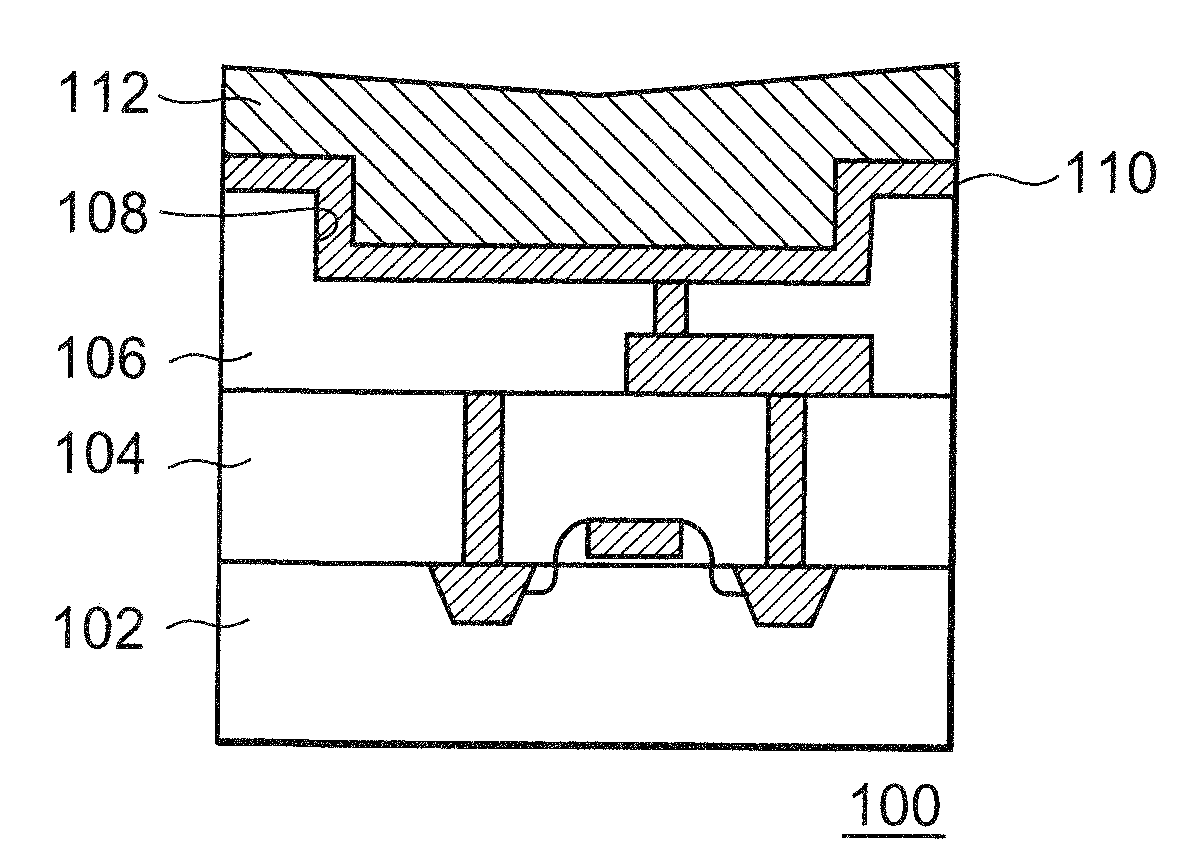
[0041]The barrier metal film 110 was immersed in the plating solution 204 with no voltage being applied between the barrier metal film 110 and the anode 202 in immersion. After one second elapsed with this state being maintained, voltage was applied between the barrier metal film 110 and the anode 202 (negative current of 100 A / m2 was applied to the barrier metal film 110) to fill in the opening 108 with a copper film.

example 2

Comparative Example

[0042]The barrier metal film 110 was immersed in the plating solution 204 with voltage being applied between the barrier metal film 110 and the anode 202 in immersion (negative current of 100 A / m2 was applied to the barrier metal film 110), and, with this state maintained, the opening 108 was filled in with a copper film.

[0043]The manufactured copper interconnect was observed with TEM. While no void was observed in Example 1, voids were observed in Example 2.

[0044]Although the embodiment of the present invention has been described above with reference to the drawings, this is merely exemplary and other various structures can be adopted.


PUM

PropertyMeasurementUnit
length of timeaaaaaaaaaa
thicknessaaaaaaaaaa
thicknessaaaaaaaaaa

Abstract

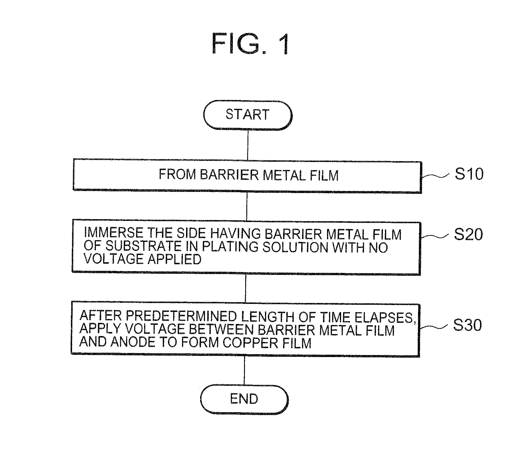
To obtain a copper film having satisfactory electrical characteristics with a simple structure, there is provided a method of manufacturing a semiconductor device including the step of forming on a semiconductor substrate a barrier metal film to be a seed film which functions as a cathode when a copper film is formed by electrolytic plating (S10), the step of immersing the barrier metal film in a plating solution containing copper ion in a plating bath for a predetermined length of time with the barrier metal film and an anode being substantially at the same potential (S20), and the step of, after the barrier metal film is immersed in the copper sulfate plating solution for the predetermined length of time, applying voltage between the barrier metal film and the anode with the barrier metal film being kept immersed in the plating solution to form a copper film on the barrier metal film (S30).

Description

BACKGROUND OF THE INVENTION[0001]1. Field of the Invention[0002]The present invention relates to a method of manufacturing a semiconductor device.[0003]2. Description of Related Art[0004]In recent semiconductor devices, delay in signal transmission on interconnects may sometimes determine operation speed of LSI circuits. Delay constant of signal transmission on interconnects is expressed by a product of interconnect resistance and parasitic capacitance. In order to reduce the interconnect resistance so as to enhance the operation speed of the LSI circuits, copper having a small resistivity has been becoming popular as an interconnect material.[0005]Copper multilayer interconnect may be formed by the damascene process. The damascene process generally includes a step of depositing an insulating film such as an interlayer insulating film, a step of forming an opening such as a via hole or a trench, a step of depositing a barrier metal film, a step of depositing a copper thin film to be...

Claims


Application Information

Patent Timeline
Patent Type & Authority Applications(United States)
IPC IPC(8): H01L21/44
CPCH01L21/76877H01L21/2885
Inventor FURUYA, AKIRA
Owner NEC ELECTRONICS CORP
Learn More