
Nonreciprocal circuit device and manufacturing method of the same

Active Publication Date: 2008-09-11
MURATA MFG CO LTD
View PDF2 Cites 5 Cited by
  • Summary
  • Abstract
  • Description
  • Claims
  • Application Information

AI Technical Summary

Benefits of technology

[0007]To overcome the problems described above, preferred embodiments of the present invention provide a nonreciprocal circuit device having a simple structure with simple manufacturing processes and also having satisfactory electrical characteristics, and a manufacturing method of the nonreciprocal circuit device.

Problems solved by technology

A volume ratio below about 5 vol % impairs the capability of forming a magnetic path, and a volume ratio of more than about 50 vol % decreases the wettability of the filler with the resin, resulting in insufficient mechanical strength of the resin layer.

Method used


Image

  • Nonreciprocal circuit device and manufacturing method of the same
  • Nonreciprocal circuit device and manufacturing method of the same
  • Nonreciprocal circuit device and manufacturing method of the same

Examples


first preferred embodiment

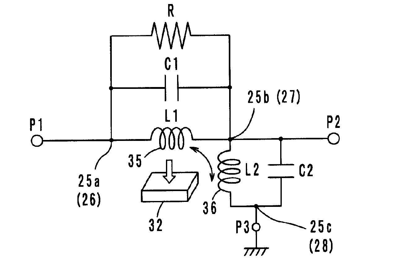
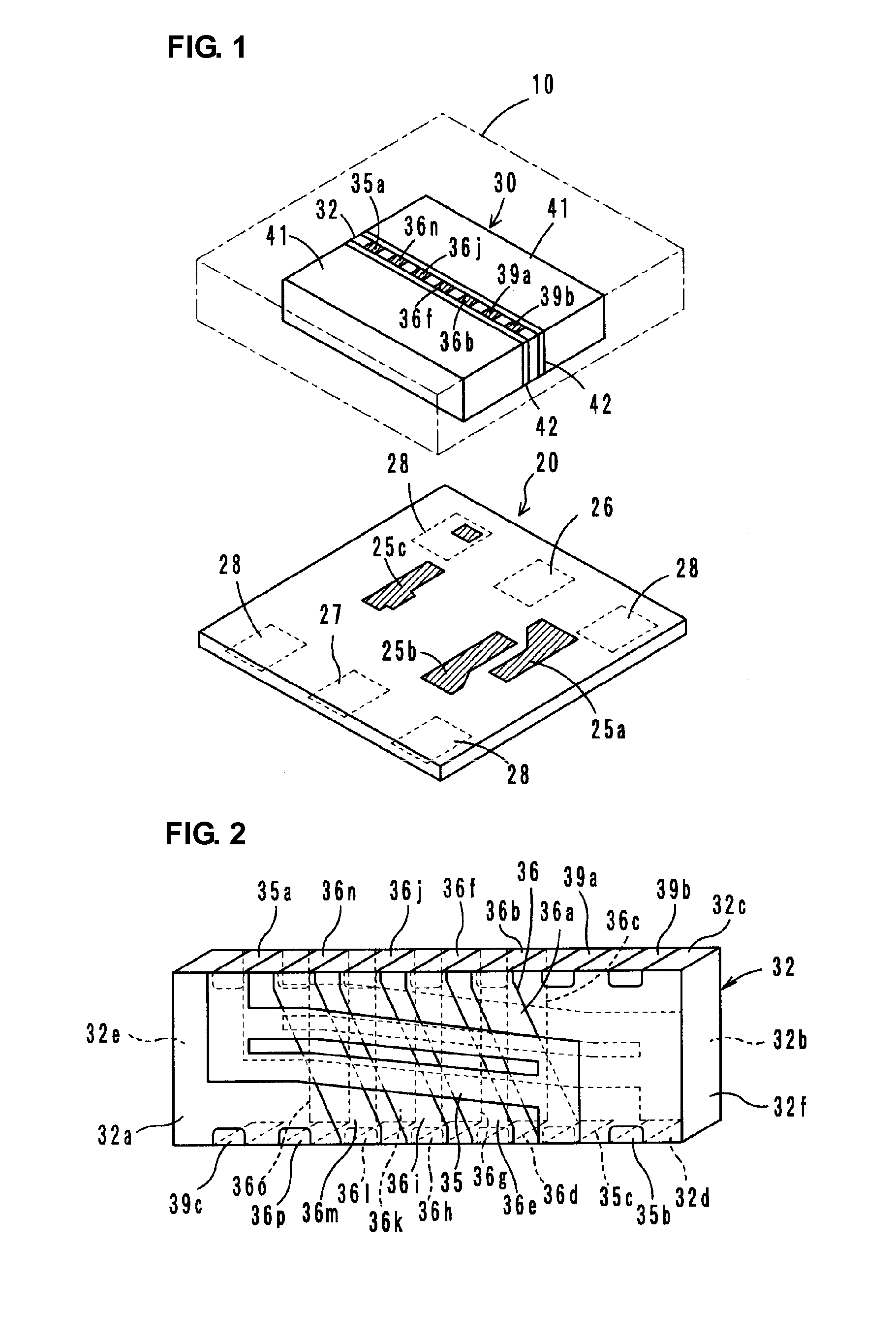
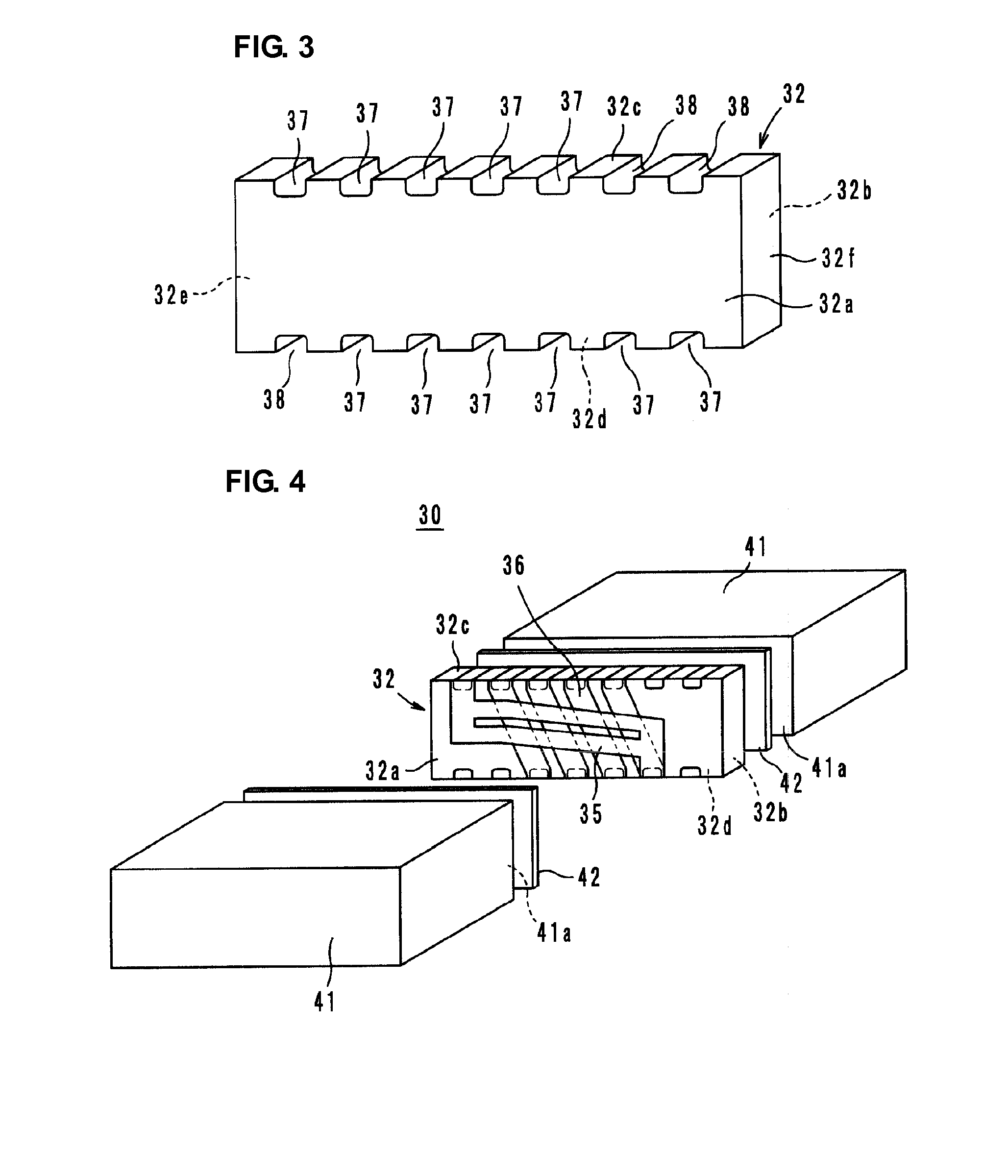
[0031]FIG. 1 shows an exploded perspective view of a two-port isolator, which is a first preferred embodiment of a nonreciprocal circuit device according to the present invention. This two-port isolator is a lumped-constant isolator which includes a circuit substrate 20 a ferrite-magnet assembly 30 including a ferrite 32 and permanent magnets 41. The outer periphery of ferrite-magnet assembly 30 is covered with a resin layer 10. In FIG. 1, components indicated by oblique lines represent conductors.

[0032]As illustrated in FIG. 2, the ferrite 32 has opposite principal surfaces 32a and 32b on which a first central electrode 35 and a second central electrode 36 electrically insulated from each other are provided. The ferrite 32 preferably has a substantially rectangular parallelepiped shape, for example, which includes the first principle surface 32a and the second principal surface 32b that are substantially parallel to each other, a top surface 32c, a bottom surface 32d, and end surfa...

second preferred embodiment

[0058]FIG. 10 shows an exploded perspective view of a two-port isolator according to a second preferred embodiment of the present invention. This two-port isolator preferably has a configuration that is similar to the first preferred embodiment, but is different from the first preferred embodiment in that it includes a tabular-shaped yoke 15 made of a magnetic material on an outer resin layer 12 defining a resin layer 10. Other than this arrangement, the configuration of the two-port isolator is similar to that of the first preferred embodiment, and a redundant description thereof is omitted.

[0059]The tabular-shaped yoke 15 may be embedded in the surface of the magnetic resin layer 12 or may be disposed on the surface of the magnetic resin layer 12. A magnetic circuit and magnetic shielding effect provided by the magnetic resin layer 12 are enhanced. In particular, leakage of magnetic flux to the outside can be prevented even when the amount of a filler mixed in the magnetic resin l...


PUM

PropertyMeasurementUnit
Magnetismaaaaaaaaaa
Volume ratioaaaaaaaaaa

Abstract

A nonreciprocal circuit device includes permanent magnets, a ferrite to which a direct current magnetic field is applied by the permanent magnets, first and second central electrodes arranged on the ferrite, and a circuit substrate. A ferrite-magnet assembly mounted on the circuit substrate is covered with a resin layer. The resin layer includes an innermost layer made of a non-magnetic resin material and a magnetic resin layer having a magnetic filler mixed therein.

Description

BACKGROUND OF THE INVENTION[0001]1. Field of the Invention[0002]The present invention relates to nonreciprocal circuit devices. In particular, the present invention relates to a nonreciprocal circuit device, such as an isolator and a circulator, preferably for use in a microwave band, and also relates to a manufacturing method of the nonreciprocal circuit device.[0003]2. Description of the Related Art[0004]Conventionally, nonreciprocal circuit devices, such as isolators and circulators, have a characteristic that allows signals to be transmitted only in a predetermined specific direction but not in the opposite direction. By making use of such characteristics, isolators, for example, are used in transmission circuits of mobile communication apparatus, such as automobile phones and portable phones.[0005]In this type of nonreciprocal circuit device, to protect an assembly of a ferrite having a plurality of central electrodes and permanent magnets applying a direct-current magnetic fie...

Claims


Application Information

Patent Timeline
IPC IPC(8): H01P1/36H01P11/00
CPCH01F2003/103Y10T29/49135H01P1/36H01F2017/048
Inventor WADA, TAKAYA
Owner MURATA MFG CO LTD
Learn More