Tap sensor for weapon simulator
- Summary
- Abstract
- Description
- Claims
- Application Information
AI Technical Summary
Problems solved by technology
Method used
Image
Examples
first embodiment
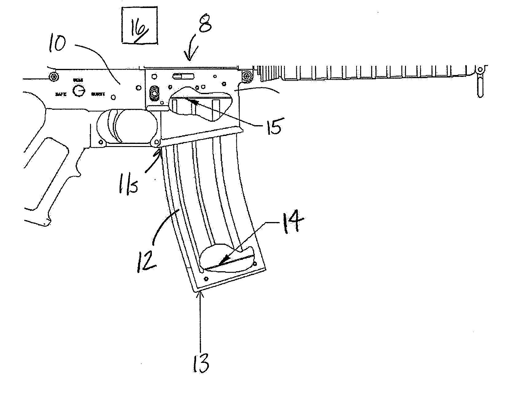
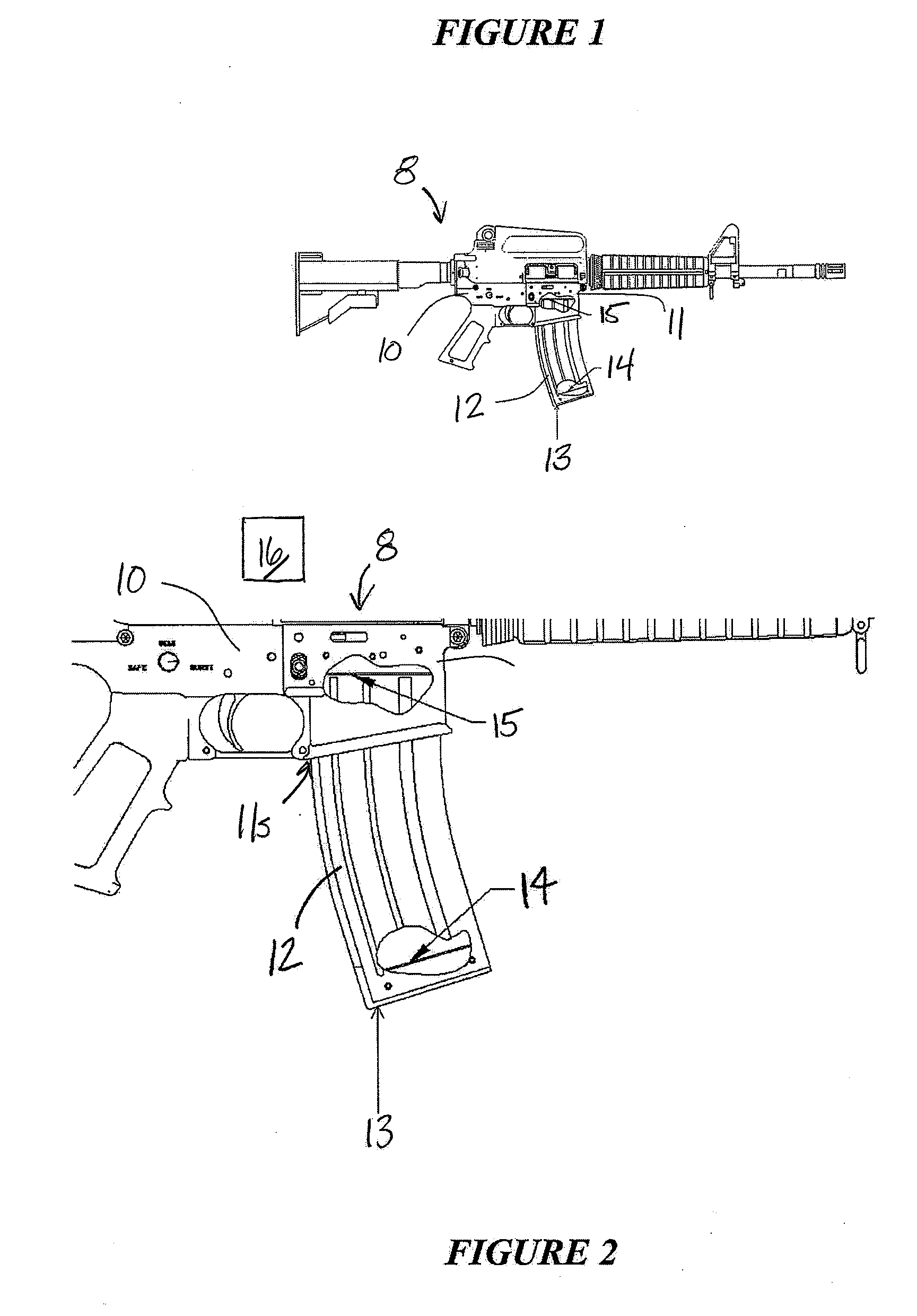
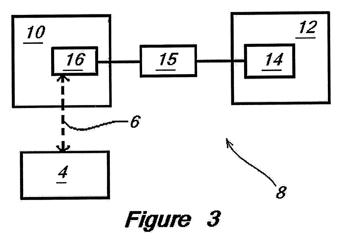
[0016]the weapon simulator assembly 8 is illustrated in FIGS. 1-3. In this embodiment, the tap sensor 14 is positioned in the magazine 12 to monitor any forces applied to the bottom of the magazine 12. The tap sensor 14 could be a pressure sensor, variable resistance sensor, shock sensor or impact sensor, among other related designs. For example, a shock or impact sensor 14 could be incorporated in the magazine 12 to detect a sudden or severe impact force and indicate whether the strength of the tap force exceeds a predetermined level. The tap sensor 14 will then provide corresponding feedback to a processor 16 in the simulated weapon 10 via an electrical interface 15 connecting the sensor 14 of the magazine 12 with the processor 16 of the firearm 10. In particular, shock sensors are a type of transducer that responds to shock energy by producing another type of energy signal, usually electrical. Such sensors 14 should be sensitive to shock but insensitive to other properties.
[0017]...
second embodiment
[0019]In the invention illustrated in FIGS. 4 and 5, the sensor 14 as described above is positioned in the magazine 12 at the interface of the magazine 12 with the simulated weapon 10. The sensor 14 is placed at the interface between the magazine 12 and the simulated weapon 10 so that the force generated by striking the bottom of the magazine 12 will cause a corresponding change of state in the sensor 14. This change of state is transmitted to the processor 16 in the simulated weapon 10, and is recognized by the processor 16 in the simulated weapon 10 as a tap force that occurred to correct the malfunction of the simulated weapon 10, a corresponding signal is transmitted to central processing unit 4.
third embodiment
[0020]the present invention, illustrated in FIGS. 6, uses a tap sensor 14 for measuring motion, such as an accelerometer, that may be located in either the magazine 12 (shown in FIG. 3) or the simulated weapon 10 (shown in FIG. 7). The sensor 14 will detect a sudden acceleration in the direction of the magazine 12 movement and transmit a corresponding signal to the processor 16. The accelerometer is a sensor 14 for measuring acceleration and vibration that can be a raw sensing element, a packaged transducer, or a sensor system, with the most common types of accelerometers being piezoelectric, capacitance, null-balance, strain gage, resonance, piezoresistive or magnetic induction. The accelerometer is in electrical communication with the processor 16 of the simulated weapon 10, such that the accelerometer will monitor any rapid movement of the simulated weapon 10 or attached magazine 12. Thus, when the magazine 12 is struck in a simulation to correct the weapon malfunction, the entir...
PUM
 Abstract
Description
Claims
Application Information
 - R&D Engineer
- R&D Manager
- IP Professional
- Industry Leading Data Capabilities
- Powerful AI technology
- Patent DNA Extraction
Browse by: Latest US Patents, China's latest patents, Technical Efficacy Thesaurus, Application Domain, Technology Topic, Popular Technical Reports.
© 2024 PatSnap. All rights reserved.Legal|Privacy policy|Modern Slavery Act Transparency Statement|Sitemap|About US| Contact US: help@patsnap.com


