
Electrode material for lithium secondary battery, electrode structure and lithium secondary battery

a lithium secondary battery and electrode structure technology, applied in nickel compounds, cell components, instruments, etc., can solve the problems of difficult to new build a thermal power plant, source of air pollutants, and difficult to meet the requirements of new construction, and achieve excellent characteristics and reduce capacity degradation

Inactive Publication Date: 2008-06-05
CANON KK
View PDF40 Cites 63 Cited by
  • Summary
  • Abstract
  • Description
  • Claims
  • Application Information

AI Technical Summary

Benefits of technology

[0010]It is, therefore, an object of the present invention to provide a positive electrode active material, namely, a positive electrode material for a lithium secondary battery which has suppressed capacity degradation accompanying charging / discharging and exhibits excellent characteristics, by overcoming the above described problems and by taking advantage of the excellent characteristics of LiMO2 having the α-NaFeO2 structure.
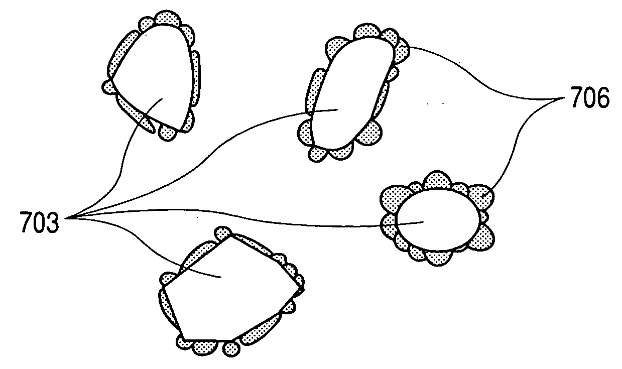
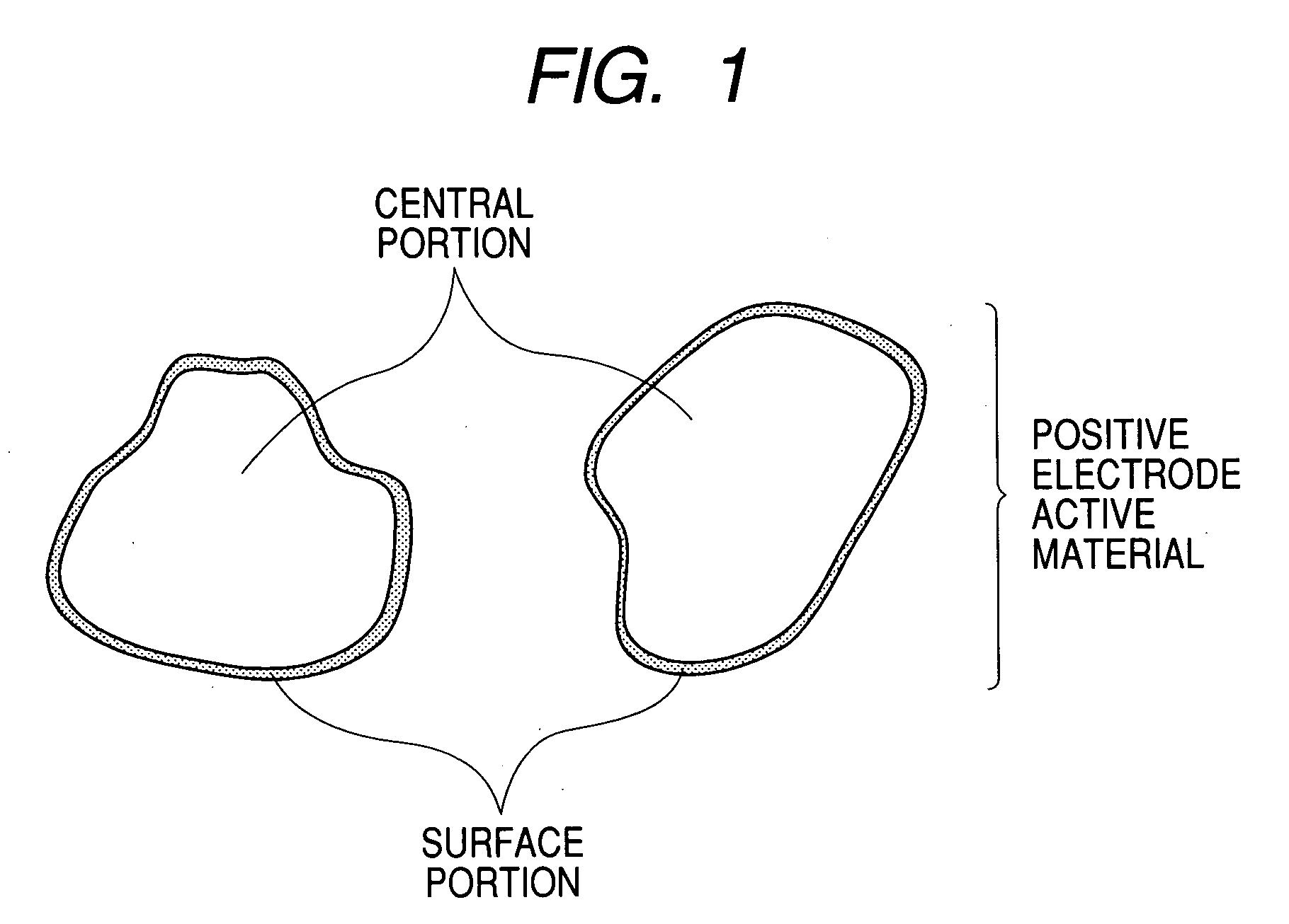
[0012]The present inventors have conducted extensive theoretical and laboratory studies for the purpose of overcoming the above-described problems involved in LiMO2 having the α-NaFeO2 structure, and have consequently found that in a state where the Li of LiMO2 (M represents Co or Ni) having the α-NaFeO2 structure is missing, the bonding between the transition metal M and oxygen in the surface of the particles of the lithium / transition-metal composite oxide is weakened. Furthermore, the present inventors have found that by adopting the configuration such that particles of the above-described lithium / transition-metal composite oxide (positive electrode active material) each form a central portion; another lithium / transition-metal composite oxide covers the surface of the central portion to form a surface portion; a part of the transition metal element of the central portion is replaced with another transition metal element or Al; and a part of the transition metal element of the surface portion is replaced with a specific element, the bonding between the transition metal and oxygen in the surfaces of the particles of the positive electrode active material can be strengthened.
[0013]More specifically, the present inventors have found that with positive electrode active material particles each having a central portion and a surface portion covering (or coating) the surface of the central portion and having an average particle diameter of 0.1 to 10.0 μm, wherein the central portion occupies 80 to 99% of a distance from a center to an outermost surface of the particle and the surface portion occupies 20 to 1% of the distance; the central portion comprises LiM1-aDaO2 (M represents Co or Ni, D represents a transition metal element or Al replacing a part of Co or Ni as M, and M is not the same as D) having an α-NaFeO2 structure; the surface portion comprises LiM1-bEbO2 (M represents Co or Ni, E represents a metal element replacing a part of Co or Ni as M, and M is not the same as E) having an α-NaFeO2 structure; the content of element E in the central portion satisfies the relation of E / (M+D+E)<0.05 in terms of an atomic ratio; the content of element D in the surface portion satisfies the relation of D / (M+D+E)<0.05 in terms of an atomic ratio, because the species of replacing element D and the value a of the central portion thus differ from the species of replacing element E and the value b of the surface portion, respectively, the bonding between the transition metal and oxygen in the surfaces of the positive electrode active material particles is strong, the high-temperature storage characteristic is excellent and the cycle characteristic is high.

Problems solved by technology

For example, a thermal power plant where a thermal energy obtained by burning fossil fuel is converted to an electric energy discharges a large amount of CO2 gas, and accordingly, it has been becoming hardly possible to newly construct a thermal power plant.
On the other hand, automobiles that run using fossil fuel emit, in addition to CO2 gas, Nox, Sox, hydrocarbons and the like, and hence are considered to be problematic as another source of release of air pollutants.
The lithium cobalt composite oxide (LiCoO2) used as the positive electrode material has a drawback that it contains cobalt, which is a nonabundant resource, as its source material and is therefore expensive, but is regarded as having a highest practical value of the existing positive electrode materials (positive electrode active materials).
This is mainly because no other alternatives to replace the lithium cobalt composite oxide have been provided yet.
Additionally, lithium nickel cobalt composite oxide (LiNi1-xCoxO2) developed for the purpose of overcoming the above-described drawback of lithium nickel composite oxide (LiNiO2) is still not sufficient in the characteristic of retention of capacity after repeated charging / discharging and is not therefore superior to the lithium cobalt composite oxide (LiCoO2).
Although the techniques involved in these applications are intended to improve the characteristics as the positive electrode active materials by substituting parts of the constituent elements of LiMn2O4 or LiCoO2 with different species of elements, these positive electrode active materials cannot be said to be sufficient in the characteristic involved in the capacity retention after repeated charging / discharging.
However, even in such positive electrode active materials with the surface-coated structures, the characteristics involved in the capacity retention after repeated charging / discharging cannot be said to be sufficient.
However, LiMO2 is liable to cause capacity degradation accompanying charging / discharging and particularly has a serious problem that repeated charging / discharging at a temperature as high as 60° C. leads to a greater capacity degradation, so that LiMO2 is not considered to be worthy of practical use.

Method used


Image

  • Electrode material for lithium secondary battery, electrode structure and lithium secondary battery
  • Electrode material for lithium secondary battery, electrode structure and lithium secondary battery
  • Electrode material for lithium secondary battery, electrode structure and lithium secondary battery

Examples


example 1

[0119]The lithium secondary battery having the configuration shown in FIG. 8 was fabricated as follows.

1. Preparation of Electrode Material (Positive Electrode Active Material)

(1) Synthesis of LiNi0.975Ti0.025O2:

[0120]Lithium citrate, nickel nitrate and tetraethoxytitanium (Ti(OC2H5)4) were weighed out in such a way that the relations Li / (N+Ti)=1.06 (atomic ratio) and Ni / Ti=97.5 / 2.5 (atomic ratio) were satisfied; then, the lithium citrate and nickel nitrate were dissolved in a 20 wt % aqueous solution of citric acid; while the aqueous solution was heated to 60° C. and being stirred, the tetraethoxytitanium (Ti(OC2H5)4) was added to the aqueous solution, and thereafter the aqueous solution thus obtained was spray-dried with the aid of a spray dryer to obtain a precursor. The thus obtained precursor was calcined at 750° C. for 12 hours in an oxygen atmosphere (supplied at a rate of 3 L / min) to synthesize LiNi0.975Ti0.025O2 for forming the central portion.

(2) Formation of LiNi0.9V0.1O2...

example 2

[0130]A lithium secondary battery was fabricated and the performance thereof was evaluated by following the same procedure as in Example 1 with the exception that the electrode material (the positive electrode active material) was prepared as described below. The evaluation results obtained are shown in Table 1.

[Preparation of Electrode Material (Positive Electrode Active Material)]

[0131]In the same manner as that in 1-(1) of Example 1, LiNi0.975Ti0.025O2 for forming the central portion was synthesized. Then, there was formed LiNi0.9Si0.1O2 as the surface portion covering the LiNi0.975Ti0.025O2 particle (hereinafter referred to as “central portion particle”). More specifically, lithium nitrate, nickel nitrate and tetraethoxysilane (Si(OC2H5)4) were dissolved in ethanol in such a way that the relations Li / (Ni+Si)=1.06 (atomic ratio) and Ni / Si=90 / 10 (atomic ratio) were satisfied; the central portion particles were dispersed in the ethanol solution in such a way that the relation (Ni+S...

example 3

[0132]A lithium secondary battery was fabricated and the performance thereof was evaluated by following the same procedure as in Example 1 with the exception that the electrode material (the positive electrode active material) was prepared as described below. The evaluation results obtained are shown in Table 1.

[Preparation of Electrode Material (Positive Electrode Active Material)]

(1) Synthesis of LiNi0.9Mn0.1O2

[0133]Lithium citrate, nickel nitrate and manganese nitrate were weighed out in such a way that the relations Li / (N+Mn)=1.06 (atomic ratio) and Ni / Mn=90 / 10 (atomic ratio) were satisfied; then, these salts were dissolved in a 20 wt % aqueous solution of citric acid; the aqueous solution was spray-dried with the aid of a spray dryer and thus the precursor was obtained. The obtained precursor was calcined at 750° C. for 12 hours in an atmosphere of oxygen (supplied at a rate of 3 L / min), and thus LiNi0.9Mn0.1O2 forming the central portion was synthesized.

(2) Formation of LiNi0...


PUM

PropertyMeasurementUnit
average particle diameteraaaaaaaaaa
thicknessaaaaaaaaaa
particle diameteraaaaaaaaaa

Abstract

An electrode material for a lithium secondary battery which includes particles each having a central portion and a surface portion covering the surface of the central portion. A distance from a center to an outermost surface of the particle is occupied 80 to 99% by the central portion and 1 to 20% by the surface portion. The central portion includes LiM1-aDaO2 having an α-NaFeO2 structure, and the surface portion includes LiM1-bEbO2 having an α-NaFeO2 structure. (M is C or Ni; D is a transition metal element or Al replacing a part of Co or Ni as M; E is a metal element replacing a part of Co or Ni as M; and M is not the same as D or E.) The following relationships are satisfied in the central portion, in terms of atomic ratio: D / (M+D+E)<0.05 and E / (M+D+E)<0.05.

Description

BACKGROUND OF THE INVENTION[0001]1. Field of the Invention[0002]The present invention relates to an electrode material for a lithium secondary battery, an electrode structure using the electrode material, and a lithium secondary battery using the electrode structure. Incidentally, the designation of groups of elements in the present claims and specification is in conformity with the designation adopted in the IUPAC Periodic Table.[0003]2. Related Background Art[0004]In these years, the amount of CO2 gas contained in the atmosphere has been increasing, and there is an apprehension that the green house effect resulting therefrom leads to the global warming; thus, the countermeasure for reducing the exhaust amount of CO2 gas is being investigated on a global scale. For example, a thermal power plant where a thermal energy obtained by burning fossil fuel is converted to an electric energy discharges a large amount of CO2 gas, and accordingly, it has been becoming hardly possible to newl...

Claims


Application Information

Patent Timeline
Patent Type & Authority Applications(United States)
IPC IPC(8): H01M4/58B32B5/16G01N37/00C01G51/00C01G53/00H01M4/02H01M4/36H01M4/505H01M4/525H01M10/05
CPCC01G51/42Y10T428/2991C01G51/50C01G53/42C01G53/44C01G53/50C01P2002/52C01P2002/54C01P2002/77C01P2002/78C01P2004/61C01P2004/62C01P2004/80C01P2006/40H01M4/131H01M4/1391H01M4/366H01M4/485H01M4/525H01M2004/021H01M2004/028Y02E60/122C01G51/44Y02E60/10
Inventor HAGIWARA, KAZUNARIKAWAKAMI, SOICHIROINOUE, KATSUHIKOSUZUKI, NOBUYUKI
Owner CANON KK
Learn More