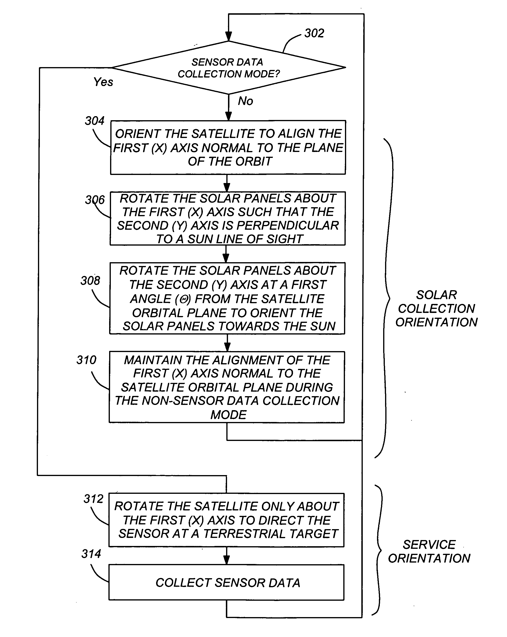
Optimal sun safe attitude for satellite ground tracking
a satellite and sun safe technology, applied in vehicle position/course/altitude control, process and machine control, instruments, etc., can solve the problems of increasing the moment of inertia of the satellite, imposing costly requirements on the satellite attitude control system, etc., to achieve simple rotation and reduce disturbance torque
- Summary
- Abstract
- Description
- Claims
- Application Information
AI Technical Summary
Benefits of technology
Problems solved by technology
Method used
Image

Examples
Embodiment Construction
[0019]In the following description, reference is made to the accompanying drawings which form a part hereof, and which is shown, by way of illustration, several embodiments of the present invention. It is understood that other embodiments may be utilized and structural changes may be made without departing from the scope of the present invention.
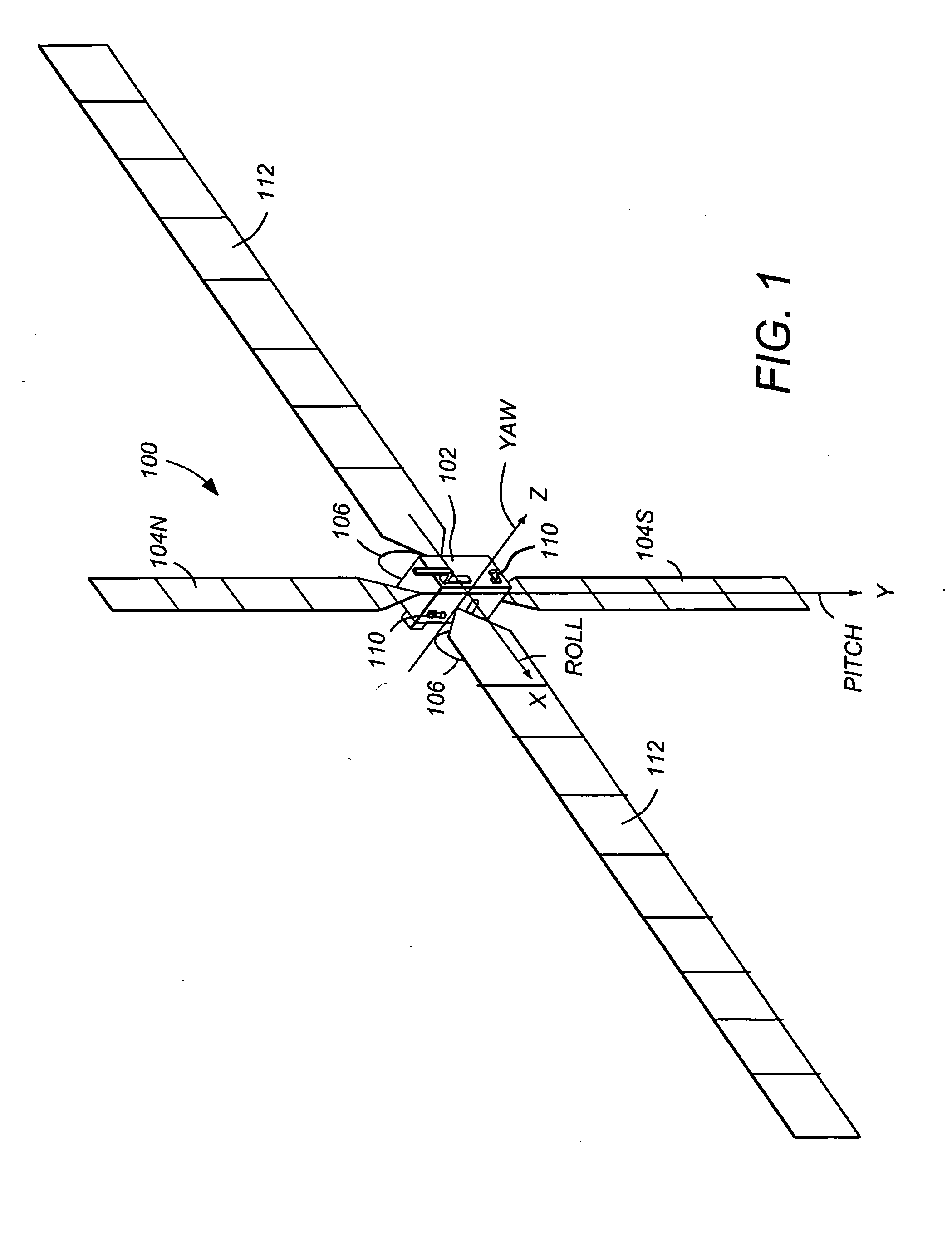
[0020]FIG. 1 illustrates a three-axis stabilized satellite or spacecraft 100. The spacecraft 100 is preferably situated in a stationary orbit about the Earth. The satellite 100 has a main body 102, a pair of solar panels 104, a pair of high gain narrow beam antennas 106, and a telemetry and command omnidirectional antenna 108 which is aimed at a control ground station. The satellite 100 may also include one or more sensors 110 to measure the attitude of the satellite 100. These sensors may include sun sensors, earth sensors, and star sensors. Since the solar panels are often referred to by the designations “North” and “South”, the solar pane...
PUM
 Abstract
Description
Claims
Application Information
 - R&D
- Intellectual Property
- Life Sciences
- Materials
- Tech Scout
- Unparalleled Data Quality
- Higher Quality Content
- 60% Fewer Hallucinations
Browse by: Latest US Patents, China's latest patents, Technical Efficacy Thesaurus, Application Domain, Technology Topic, Popular Technical Reports.
© 2025 PatSnap. All rights reserved.Legal|Privacy policy|Modern Slavery Act Transparency Statement|Sitemap|About US| Contact US: help@patsnap.com