Air conditioning system for construction or agricultural machines
a technology for air conditioning systems and agricultural machines, which is applied in the direction of railway heating/cooling, vehicle heating/cooling devices, vehicle components, etc., can solve the problems of insufficient and the heat cannot be hardly felt by the body parts out of reach, so as to prevent the effect of being frosted, convenient configuration, and improved warmth in the neighborhood of the knees and thighs of the occupants
- Summary
- Abstract
- Description
- Claims
- Application Information
AI Technical Summary
Benefits of technology
Problems solved by technology
Method used
Image


Examples
first embodiment
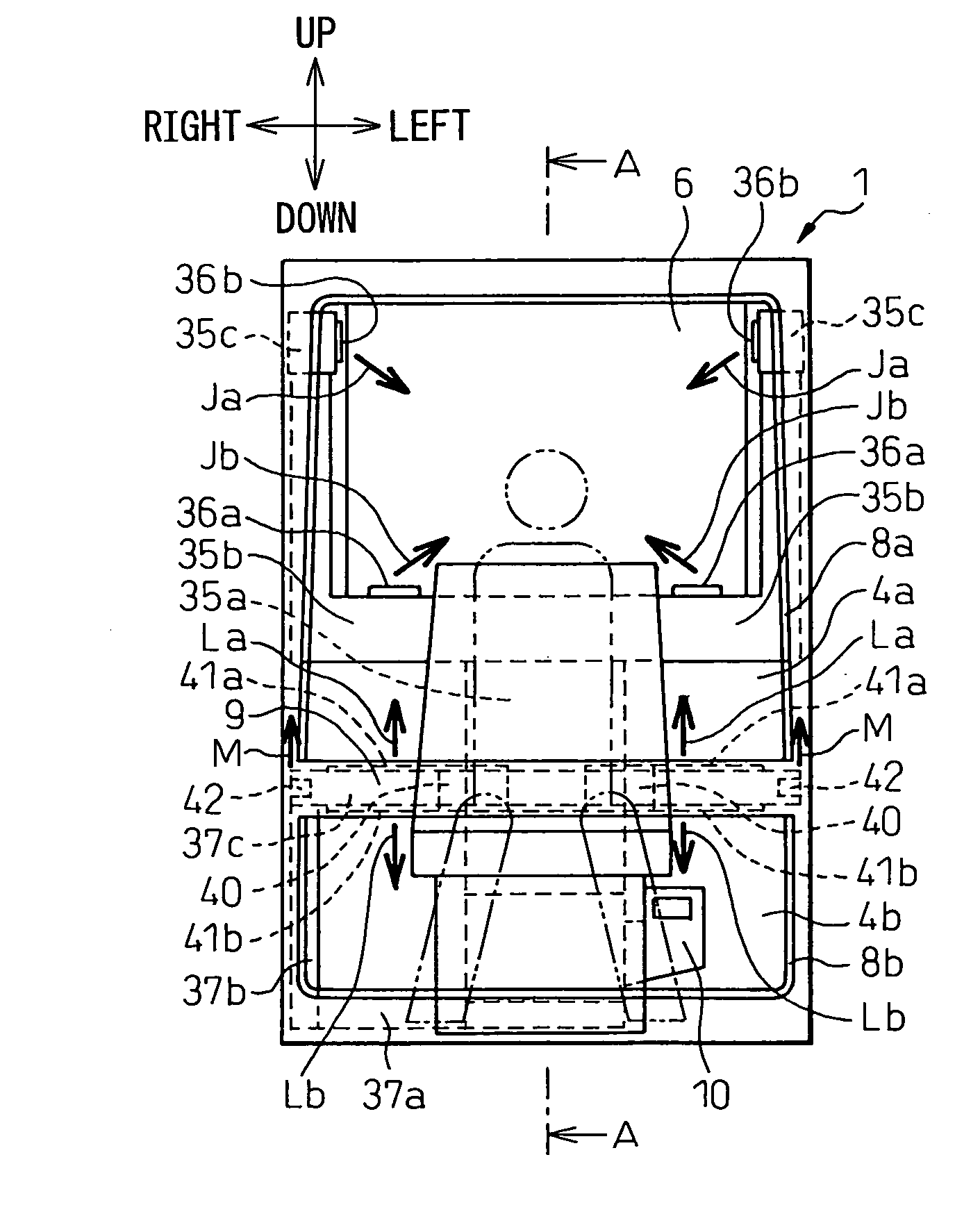
[0042]FIGS. 1A and 1B are diagrams showing a general configuration of an air conditioning system for a hydraulic shovel, as a construction or agricultural machine, according to a first embodiment of the invention. FIG. 1A is a front view schematically showing a cabin 1 of the hydraulic shovel according to this embodiment, and FIG. 1B a sectional view taken in line A-A in FIG. 1A.
[0043]In FIGS. 1A and 1B, two-dot chain lines schematically show an occupant taking the seat 3 arranged at substantially the central portion on the floor 2 of the cabin 1. The arrows “front / rear”, “up / down” and “left / right” designate the directions “front / rear”, “up / down” and “left / right”, respectively, as viewed from the seated occupant in the cabin 1. The description that follows is based on these directions as viewed from the occupant.
[0044]The cabin 1 of the hydraulic shovel includes a windshield 4 on the front side, side window glass 5 on the left and right sides, rear window glass 6 on the rear side, a...
second embodiment
[0114]According to the first embodiment described above, the rail 9 and the third duct portion 37c are formed as separate members and fixed to each other with screws. According to the second embodiment, on the other hand, the rail 9 and the third duct portion 37c are eliminated, and a rail 90 shown in FIG. 4 is used in place. The other parts of the configuration are similar to those of the first embodiment.
[0115]FIG. 4 is a perspective view of the rail 90 as taken from the upper left point in the cabin 1. The rail 90 is a substantially parallelopipedal member having an internal hollow space. The lower end side of the upper windshield 4a and the upper end side of the lower windshield 4b are fixed on the font surface 90a of the rail 90. Thus, the rail 90 makes up a frame member according to this embodiment.
[0116]Further, a second foot air duct joint 38a is arranged on the lower right end surface of the rail 90 and is connected with the rail 90 side end of the second duct portion 37b. ...
third embodiment
[0123]According to the first embodiment described above, the air-conditioning air from the air-conditioning unit 10 is blown out from the first and second face air outlets 36a, 36b through the face air duct 35, and at the same time, blown out from the foot air outlets 40, the defroster air outlets 41a, 41b and the side window defroster air outlets 42 through the foot air duct 37. According to the third embodiment, on the other hand, the system further includes a second foot air duct 43 and a second foot air outlet 44 as shown in FIGS. 5A, 5B. The other parts of the configuration are similar to those of the first embodiment.
[0124]FIG. 5A is a front view schematically showing the cabin 1 of the hydraulic shovel according to this embodiment, and FIG. 5B a sectional view taken in line N-N in FIG. 5A. Also, in FIGS. 5A and 5B, the component parts having the functions identical or equivalent to those in the general configuration of the first embodiment (FIG. 1) are designated by the same ...
PUM
 Abstract
Description
Claims
Application Information
 - R&D
- Intellectual Property
- Life Sciences
- Materials
- Tech Scout
- Unparalleled Data Quality
- Higher Quality Content
- 60% Fewer Hallucinations
Browse by: Latest US Patents, China's latest patents, Technical Efficacy Thesaurus, Application Domain, Technology Topic, Popular Technical Reports.
© 2025 PatSnap. All rights reserved.Legal|Privacy policy|Modern Slavery Act Transparency Statement|Sitemap|About US| Contact US: help@patsnap.com