Tubular Member Fixing Device
- Summary
- Abstract
- Description
- Claims
- Application Information
AI Technical Summary
Benefits of technology
Problems solved by technology
Method used
Image

Examples
first embodiment
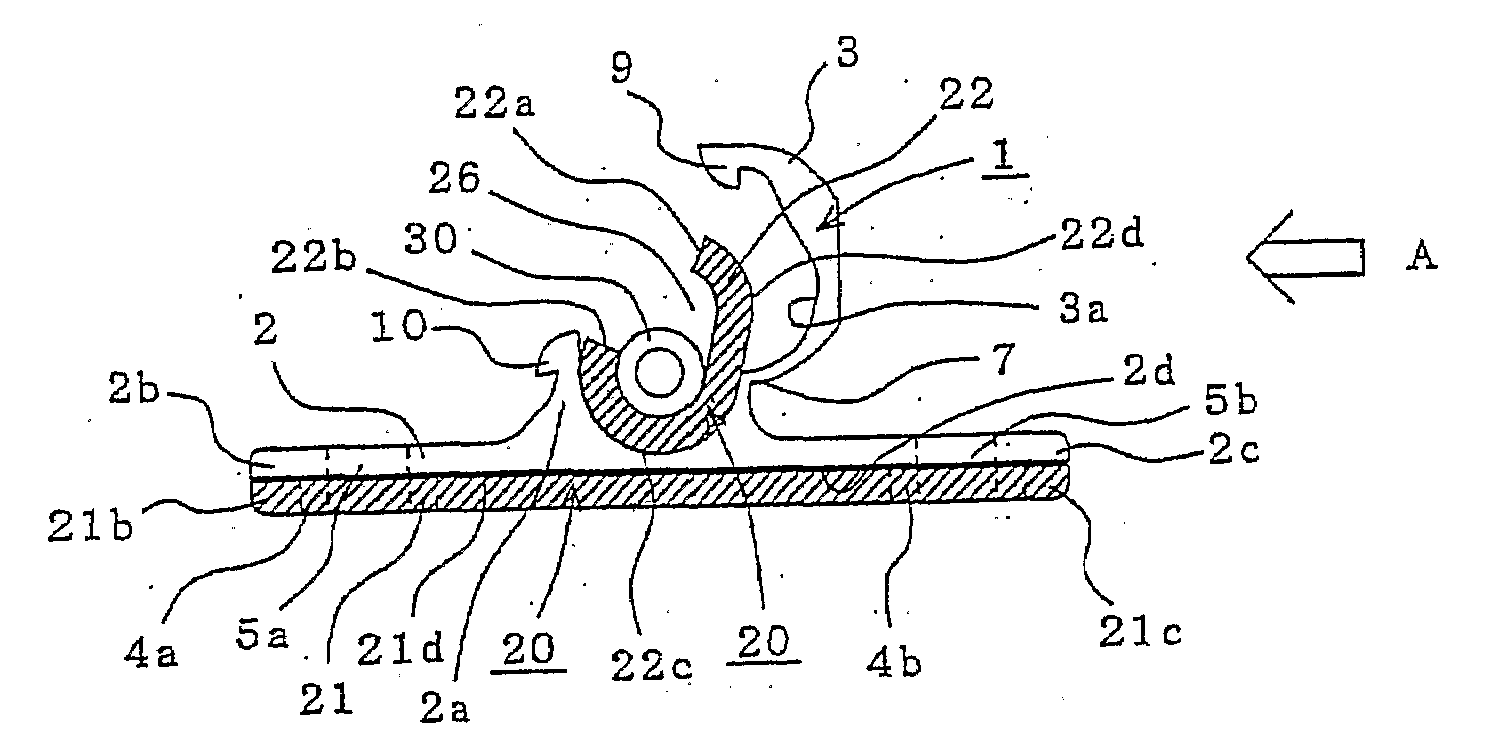
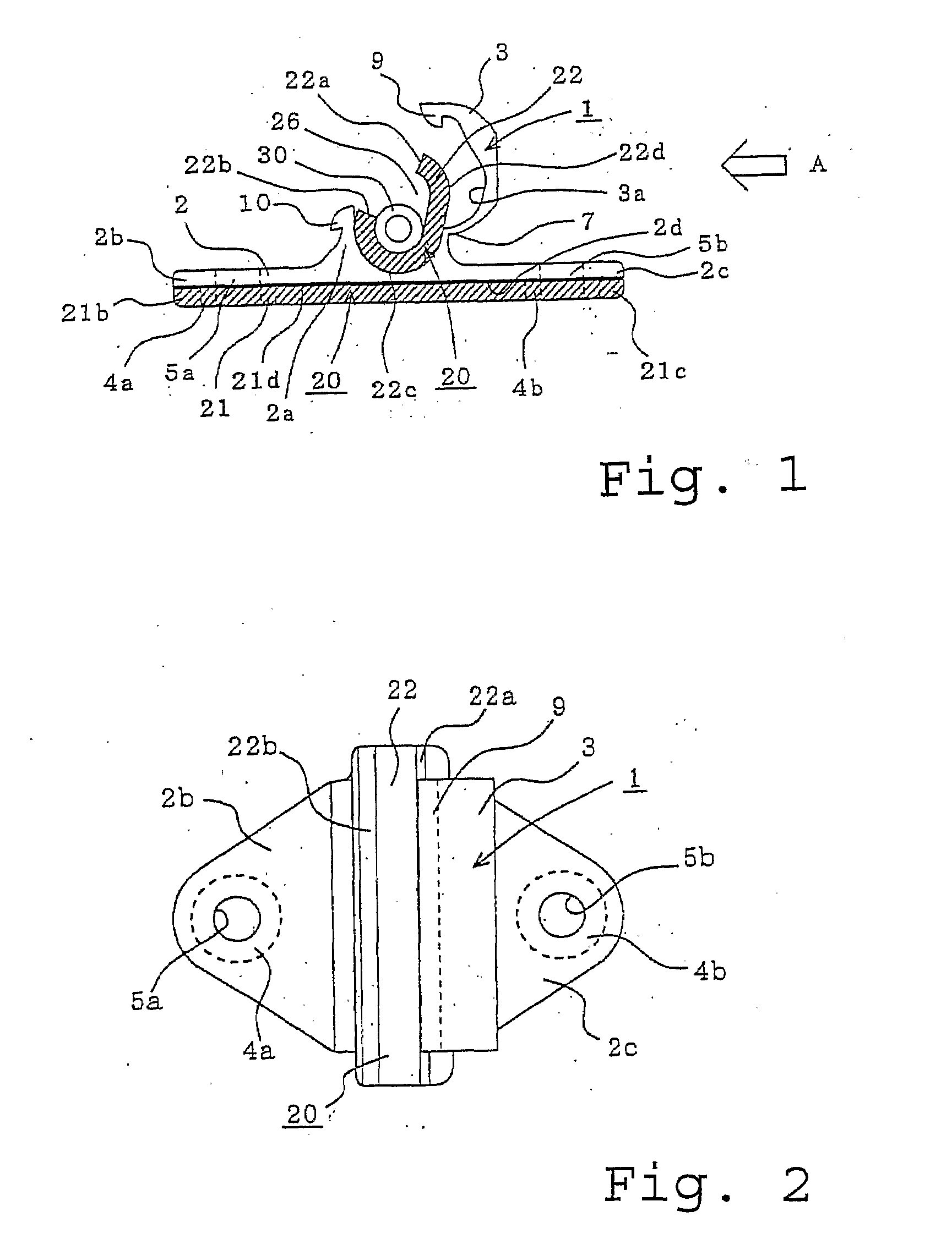
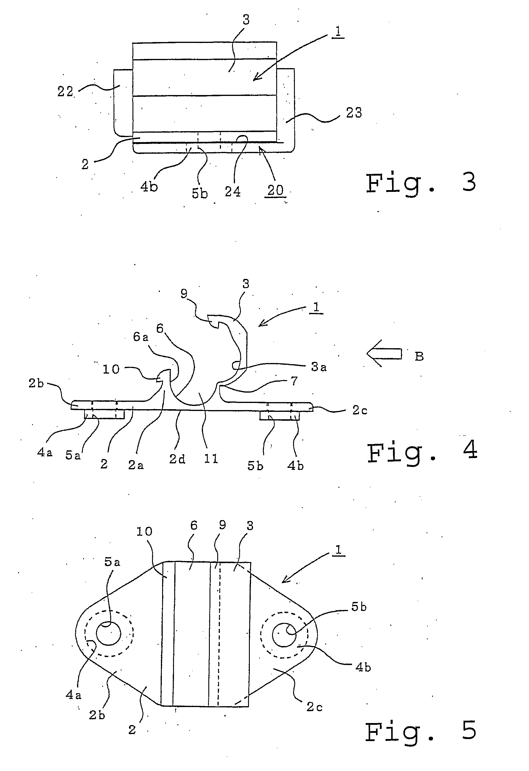
[0018]FIG. 1 is a front view of the first embodiment of the present invention, a catheter fixing device with an outer fixing member and an inner fixing member fitted and integrated with each other. FIG. 2 is a plan view of FIG. 1. FIG. 3 is a side view of FIG. 1 when viewed in the direction A. FIG. 4 is a front view of the outer fixing member which constitutes the catheter fixing device in FIG. 1. FIG. 5 is a plan view of FIG. 4. FIG. 6 is a side view of FIG. 4 when viewed in the direction B. FIG. 7 is a front view of the inner fixing member which constitutes the catheter fixing device in FIG. 1. FIG. 8 is a plan view of FIG. 7, and FIG. 9 is a side view of FIG. 7 in the direction C.
[0019]The catheter fixing device includes an outer fixing member 1 (FIG. 4 to FIG. 6) formed of material which is relatively hard and is hard to deform so as not to be broken even when it is bent, and an inner fixing member 20 (FIG. 7 to FIG. 9) formed of flexible soft vinyl chloride, and is formed by co...
second embodiment
[0030]FIG. 12 is a front view of the outer fixing member 1 constituting the catheter fixing device according to a second embodiment. In the first embodiment, the first engaging portion 9 is provided on the covering portion 3 of the outer fixing member 1, and the second engaging portion 10 is further provided on the side of the fitting joint 2a, so that the first and second engaging portions 9, 10 are engaged at a side surface of the catheter fixing device. However, in the second embodiment, a pair of covering portions 3a, 3b are provided so as to face each other, and these covering portions 3a, 3b are engaged at the top position of the catheter fixing portion. When the device is attached to the skin, and the tubular member 30 requires adjustment, the device can be opened by squeezing the covering portions 3a, 3b toward one another. In this manner, no force normal to the skin is applied, thus achieving a pain-free, irritation-free catheter 30 exchange for the patient.
[0031]In FIG. 12...
third embodiment
[0034]FIG. 14 is a front view of the inner fixing member 20 according to a third embodiment of the present invention. In the first embodiment, the retaining portion 22 is substantially cylindrical, having constant thickness in the closed state. However, in the third embodiment, protrusions 22e oriented in the axial direction are provided at regular intervals on the outer surface of the substantially cylindrical retaining portion 22. In this case, the thickness of the retaining portion 22 other than the projections 22e is configured to be thinner than the thickness of the retaining portion 22 shown in the first embodiment.
[0035]In the arrangement as described above, a pressing energy exerted by the covering portion 3 when the outer surface of the retaining portion 22 is covered by the covering portion 3 of the outer fixing member 1 can be absorbed. In particular, when the tubular member 30 is thick, the pressure generated thereby can be absorbed by the projections 22e of the retainin...
PUM
 Abstract
Description
Claims
Application Information
 - R&D
- Intellectual Property
- Life Sciences
- Materials
- Tech Scout
- Unparalleled Data Quality
- Higher Quality Content
- 60% Fewer Hallucinations
Browse by: Latest US Patents, China's latest patents, Technical Efficacy Thesaurus, Application Domain, Technology Topic, Popular Technical Reports.
© 2025 PatSnap. All rights reserved.Legal|Privacy policy|Modern Slavery Act Transparency Statement|Sitemap|About US| Contact US: help@patsnap.com