
Method for improved single event latch up resistance in an integrated circuit

a single-event latching and integrated circuit technology, applied in the field of integrated circuits, can solve the problems of damage to the integrated circuit, parasitic device formation, inadvertent formation of parasitic device,

Active Publication Date: 2008-05-29
INTEGRATED DEVICE TECH INC
View PDF0 Cites 10 Cited by
  • Summary
  • Abstract
  • Description
  • Claims
  • Application Information

AI Technical Summary

Benefits of technology

The present invention provides a method for predicting when a single event latch-up will occur in a circuit. This is done by identifying multiple junctions and a tap for each junction in the circuit. The method involves estimating the resistance of each junction in a first set of junctions, identifying which junctions are not in the first set, and outputting the estimated resistance and the location of each junction in the second set of junctions. This can help in identifying which parts of the circuit are more prone to latch-up and take appropriate measures to prevent it.

Problems solved by technology

A parasitic device may be inadvertently formed in any location of the integrated circuit by placing two or more devices in close proximity.
Because the majority carriers created in the substrate by the triggering event may outnumber the carriers created in other devices, not all majority carriers in the substrate may re-combine, causing the majority carriers in the substrate to begin collecting in the substrate.
Similar events may cause a parasitic device to form in a well on an IC.
The current flow caused by an SEL may damage the integrated circuit.
For example, the excessive current caused by an SEL may flow through the created low-impedance path, possibly causing the circuit to be destroyed by the excessive current flow.
As technology trends towards developing smaller and higher performance integrated circuits, CMOS devices become more susceptible to SELs.
The testing, however, can only indicate whether an SEL has occurred; it cannot detect where the SEL occurs in the integrated circuit unless the circuit is simultaneously functionally tested under the neutron beam using a test program.
Moreover, the testing at IROC is costly and time consuming, and may require waiting for a period in which the facility is available for such testing (about twice a year); preparing the boards, hardware, and programming for testing at IROC may also require significant time.

Method used


Image

  • Method for improved single event latch up resistance in an integrated circuit
  • Method for improved single event latch up resistance in an integrated circuit
  • Method for improved single event latch up resistance in an integrated circuit

Examples


Embodiment Construction

[0018]It is to be understood that both the foregoing general description and the following detailed description are exemplary and explanatory only and are not restrictive to the invention, as claimed. These and other embodiments are further discussed below with reference to the accompanying drawings, which are incorporated in and constitute a part of this specification.

[0019]FIG. 2 shows a PNP structure in which a tap has been placed in the substrate to prevent the parasitic PNPN structure from forming. As shown in FIG. 2, PNP structure 200 includes two P doped regions 210 and 215, N doped substrate 205, junction 207 between P doped region 210 and substrate 205, and substrate tap 220. When excess carriers are present in the substrate, a voltage may arise across substrate 205 as a function of the resistance of substrate 205 between junction 207 and tap 220. For example, during a triggering event, excess carriers 201 may collect in substrate 205 with some of excess majority carriers 2...


PUM


Abstract

A process and system for estimating the occurrence of single event latch-up in an integrated circuit. The process involves determining the resistance between each junction and the closest appropriate tap in a regular shaped well. Each junction occurring in an irregular-shaped well is also identified. Finally, the method may make suggestions for lowering the probability that single event latch-up may occur in the integrated circuit.

Description

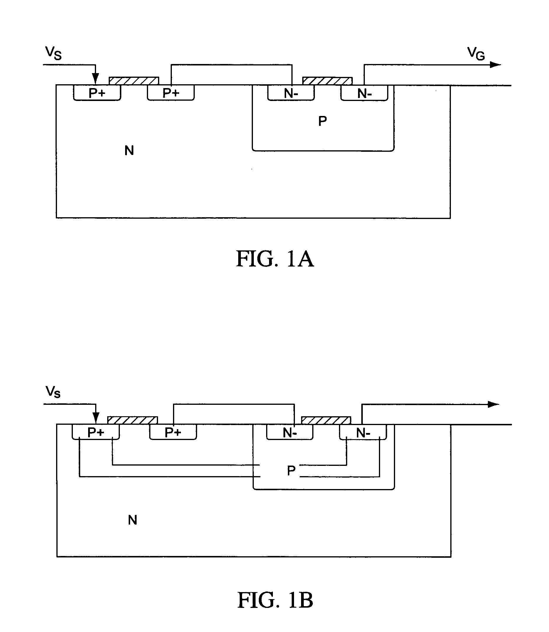
BACKGROUND[0001]1. Field of the Invention[0002]The present invention relates to integrated circuits and, in particular, to detecting and preventing the effects of a single event latch-up in an integrated circuit.[0003]2. Discussion of Related Art[0004]A latch-up occurs when an unintended path is created in an integrated circuit by triggering a parasitic device within the integrated circuit (“IC”). A parasitic device may be inadvertently formed in any location of the integrated circuit by placing two or more devices in close proximity. For example, a parasitic device or structure may occur when a PNPN structure is inadvertently formed, resulting in a silicon-controlled rectifier (SCR). FIG. 1A, for example, shows an integrated circuit with a PNP / NPN structure that may inadvertently result in a parasitic device with a PNPN structure. In FIG. 1A, each PN junction may have a diode drop voltage of 0.6 V.[0005]A single event latch-up (SEL) may be caused in an IC by a number of triggering ...

Claims


Application Information

Patent Timeline
Patent Type & Authority Applications(United States)
IPC IPC(8): G01R31/28G06F17/50
CPCG06F17/5036G01R31/2853Y10S257/929G06F30/367
Inventor LIEN, CHUEN-DERTIEN, TA-KEHUANG, PAO-LU LOUIS
Owner INTEGRATED DEVICE TECH INC
Learn More