
Radio Network Controller, Wireless Access Gateway, Radio Communication System, and Communication Method for Radio Communication System

a radio communication system and wireless access technology, applied in the field of radio network controllers, wireless access gateways, radio communication systems, and communication methods for radio communication systems, can solve the problems of lost calls, the capacity of the access point or base station of the cell cannot be exceeded, and the general inability of mobile terminals to know the status of usage of nodes in the network

Active Publication Date: 2008-05-22
SOVEREIGN PEAK VENTURES LLC
View PDF11 Cites 131 Cited by
  • Summary
  • Abstract
  • Description
  • Claims
  • Application Information

AI Technical Summary

Benefits of technology

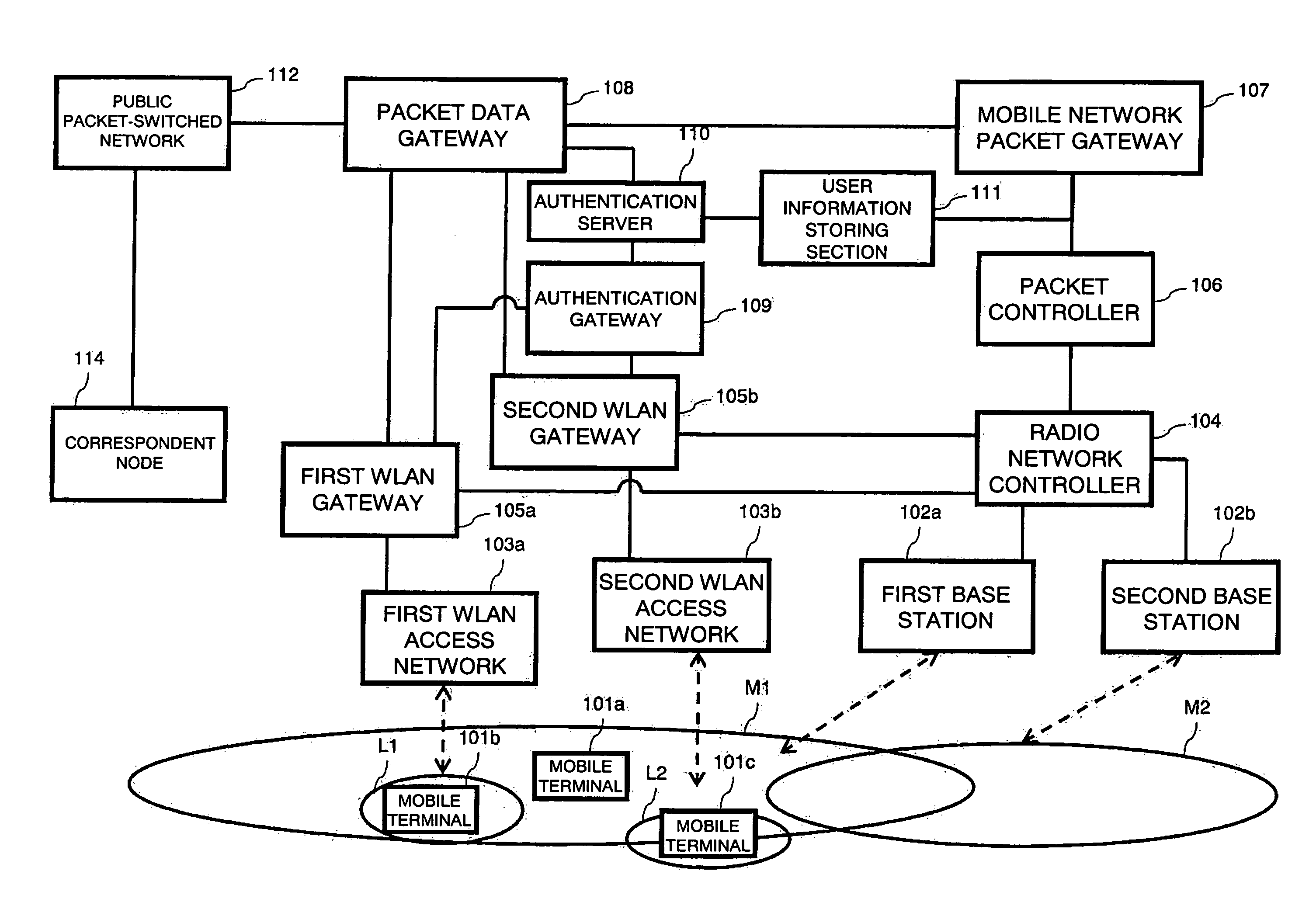
[0006]A radio network controller 2604 is connected to base stations 2602 (also referred to as the first base station 2602a and the second base station 2602b) through IP and performs wireless terminal control and transfers control data and user data. The radio network controller 2604 is RNC (Radio Network Controller) in the 3GPP specifications. Advantageous effects of the present invention can be achieved in ATM connection with base stations 2602 as well.
[0007]A first WLAN gateway 2605a and a second WLAN gateway 2605b are connected with the first WLAN access network 2603a and the second WLAN access network 2603b, respectively, and transmit control data and user data for a wireless LAN to and from their respective WLAN access networks 2603. The first WLAN gateway 2605a and the second WLAN gateway 2605b represent WAG (Wireless Access Gateway) in the 3GPP specifications. Both are collectively called the WLAN gateway 2605. The WLAN gateways represent the wireless network controller in the attached claims.
[0008]A packet controller 2606 is connected to the radio network controller 2604, controls packet transmission within the mobile communication network and manages the status of mobile terminals 2601 that relates to packet transmission. It is assumed here that the packet controller 2606 uses IP to connect to the radio network controller 2604. The packet controller 2606 represents SGSN (Serving GPRS Support Node) in the 3GPP specifications.
[0009]A mobile network packet gateway 2607 is connected with the WLAN access networks 2603 through IP and relays packet data from the mobile communication network to the Internet. The mobile network packet gateway 2607 represents GGSN (Gateway GPRS Support Node) in the 3GPP specifications. One mobile network packet gateway 2607 is provided for each APN (Access Point Name) that is a domain of the mobile terminal 2601.
[0010]A packet data gateway 2608 is connected with the mobile network packet gateway 2607 and the WLAN gateways 2605 and relays data from these gateways to a public packet-switched network 2612. Like the mobile packet gateway 2607, the packet data gateway 2608 supports APN. It is assumed here that one packet data gateway 2608 is connected with multiple WLAN gateways 2605.
[0011]An authentication gateway 2609 is connected to the WLAN gateways 2605 and receives authentication data from the mobile terminal 2601 through the WLAN gateway 2605 when the mobile terminal 2601 enters the area covered by the wireless LAN. The authentication gateway 2609 represents AAA Proxy in the 3GPP specifications.

Problems solved by technology

Mobile terminals in general cannot know the status of usage of nodes in a network.
As a result, the capacity of the access point or base station of that cell or the bandwidth of the network can be exceeded, or congestion, or in the worst case, lost calls can occur.
Therefore, the method based on mobile IP that manages mobility by IP routing is difficult to apply.

Method used


Image

  • Radio Network Controller, Wireless Access Gateway, Radio Communication System, and Communication Method for Radio Communication System
  • Radio Network Controller, Wireless Access Gateway, Radio Communication System, and Communication Method for Radio Communication System
  • Radio Network Controller, Wireless Access Gateway, Radio Communication System, and Communication Method for Radio Communication System

Examples


first embodiment

[0131]In a first embodiment, an authentication process and connection setup process are performed before a mobile terminal performing packet communication moves from a mobile communication network to an area covered by a wireless local area network (WLAN), thereby reducing switching time.

[0132]Two specific processes are performed: in one process, a radio network controller uses the phone number (IMSI: International Mobile Subscriber Identity) of a mobile terminal to set connection information on a wireless LAN on behalf of the terminal; in the other process, the radio network controller obtains connection information required for the terminal through a wireless LAN gate way (hereinafter referred to as a “WLAN gateway”) and transfers it to the terminal.

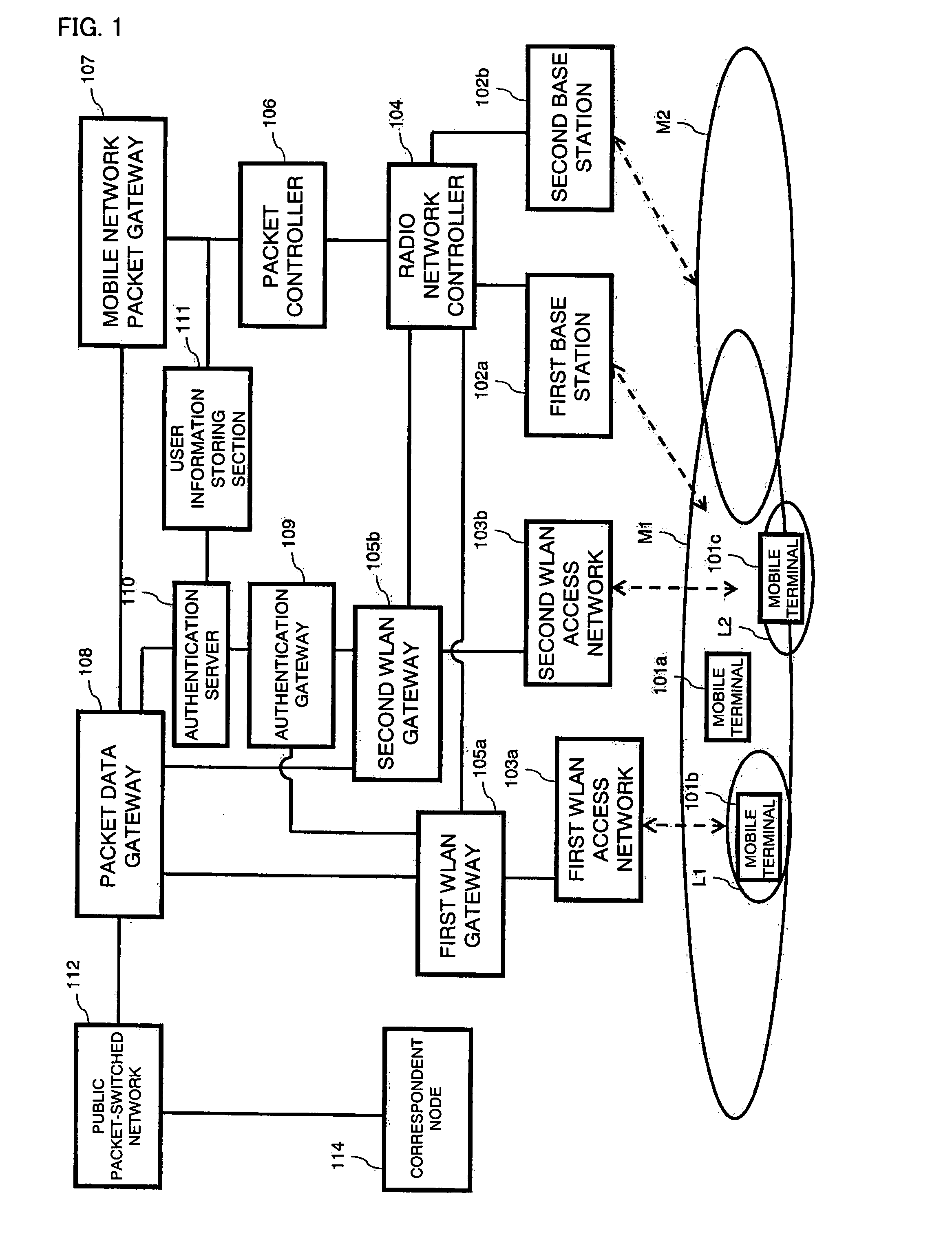
[0133]FIG. 1 shows a configuration of a radio communication system according to the first embodiment.

[0134]A public packet-switched network 112 is a packet-switched network that is open to the public. Examples of the public packet-swit...

second embodiment

[0258]In a second embodiment, packet transmission is stopped when the strength of radio signals transmitted over a wireless LAN becomes weak during communication and communication over the wireless LAN becomes impossible. The block diagrams showing the configuration of the second embodiment are the same as those in the first embodiment and therefore detailed description of the configuration thereof will be omitted.

[0259]Referring to FIG. 13, operation of the second embodiment will be described. In a first WLAN access network 103a, disconnection of packet transmission is detected after frames with the MAC address of a terminal 101b have not received for a predetermined period of time (Detect disconnection 1310). Specifically, a timer is started upon reception of a frame and the timer is updated each time a frame with the MAC address of the terminal 101b is received. When the timer expires and disconnection is detected, the first WLAN access network 103a sends a WLAN disconnection not...

third embodiment

[0269]In a third embodiment, an example is shown in which when a terminal that performs packet communication is powered on in the area covered by a wireless LAN, the terminal is registered with a mobile communication network and a wireless LAN network and starts communication and, as a result, switching time in a connection setup process performed when the terminal moves from the wireless LAN coverage area to the mobile terminal coverage are is reduced. The entire block configuration and protocol stacks in the third embodiment are the same as those in the first embodiment unless otherwise stated.

[0270]While it is assumed in the first embodiment that a terminal has already established connection with a packet controller 106 in the initial state and then moves from the mobile communication network to a wireless LAN, it is assumed in a third embodiment that a terminal attempts to establish connection to a wireless LAN immediately after its power on. Therefore, unlike the first embodime...


PUM


Abstract

A radio network controller (104) according to the present invention outputs a context required for a terminal (110a) capable of communicating with a mobile communication network and a wireless local area network to communicate with the wireless local area network to the terminal (110a) among pieces of information input from wireless access gateways (105a, 105b) that control connection with one or more wireless local area networks (103a, 103b) and provide seamless handover of packet communication between the mobile communication network and the wireless LAN.

Description

TECHNICAL FIELD[0001]The present invention relates to a handover technique for maintaining communication when moving from one network to another network of different type during the communication in an interworking system between networks of different types such as mobile communication network such as W-CDMA and a wireless LAN.BACKGROUND ART[0002]Engineers are working to develop a system that allows mobile phones capable of communicating in a wide area to interwork with a public wireless LAN service which enables fast data communication in a small area to complement each other. For example, a service is being contemplated that uses a terminal capable of accessing both mobile phone network and wireless local area network (WLAN) in such a system. This service uses a mobile communication network which covers a wide area around a base station to maintain a connection while the mobile phone is moving fast whereas it uses a wireless LAN to provide broadband access while the mobile phone i...

Claims


Application Information

Patent Timeline
Patent Type & Authority Applications(United States)
IPC IPC(8): H04Q7/24H04W12/06H04L12/46H04L45/851H04W12/00H04W28/16H04W40/34H04W48/18H04W60/00H04W76/00H04W76/02H04W76/04H04W84/12H04W88/12H04W92/02
CPCH04W12/06H04W92/02H04W84/12H04W12/062H04W12/069
Inventor ISHII, HIDENORISENGA, SATOSHIISHIDA, HIROSHIKANAZAWA, TAKESHI
Owner SOVEREIGN PEAK VENTURES LLC
Learn More