
Flat surface air bearing assembly

a technology of air bearings and flat surfaces, which is applied in the direction of maintaining the alignment of the head carrier, manufacturing tools, instruments, etc., can solve the problems of affecting the overall structural integrity of the air bearing assembly, affecting the accuracy of air bearings, and exceedingly difficult to bore small diameter holes through hard materials such as granite, and achieves low tolerance flatness.

Inactive Publication Date: 2008-05-22
CORNING INC
View PDF3 Cites 15 Cited by
  • Summary
  • Abstract
  • Description
  • Claims
  • Application Information

AI Technical Summary

Benefits of technology

[0007]The method describes how to assemble an air bed assembly. Once assembled, the entire air bearing assembly provides the same rigidity as a single piece air bearing assembly, while allowing air services to reach the upper surface of the upper portion. The multiple piece base assembly allows for multiple small diameter holes in a thinner, upper portion of granite or similar material, and provides the proper rigidity to achieve low tolerance flatness on the upper surface of the base assembly.

Problems solved by technology

Without the vacuum holes, air pressure is more likely to build up at the center of the substrate because air provided via the air holes does not readily escape from between the substrate and the air bearing assembly.
Unfortunately, boring the air and vacuum holes through the entire assembly weakens the overall structural integrity of the air bearing assembly.
Further, it is exceedingly difficult to bore a small diameter hole through a hard substance such as granite.
Among the problems encountered with drilling such holes is the likelihood of the hole not extending in a proper axial direction (such as perpendicular to the flat upper surface of the granite), the holes being of improper cross-sectional shape (e.g., oval instead of circular), or the drill bit used to bore the hole being damaged.
As the overall structural integrity of the air bearing assembly is important for maintaining a stable, flat upper surface of the assembly (e.g., to manipulate and process the substrate), the conventional surface assembly has not been entirely satisfactory.

Method used


Image

  • Flat surface air bearing assembly
  • Flat surface air bearing assembly
  • Flat surface air bearing assembly

Examples


Embodiment Construction

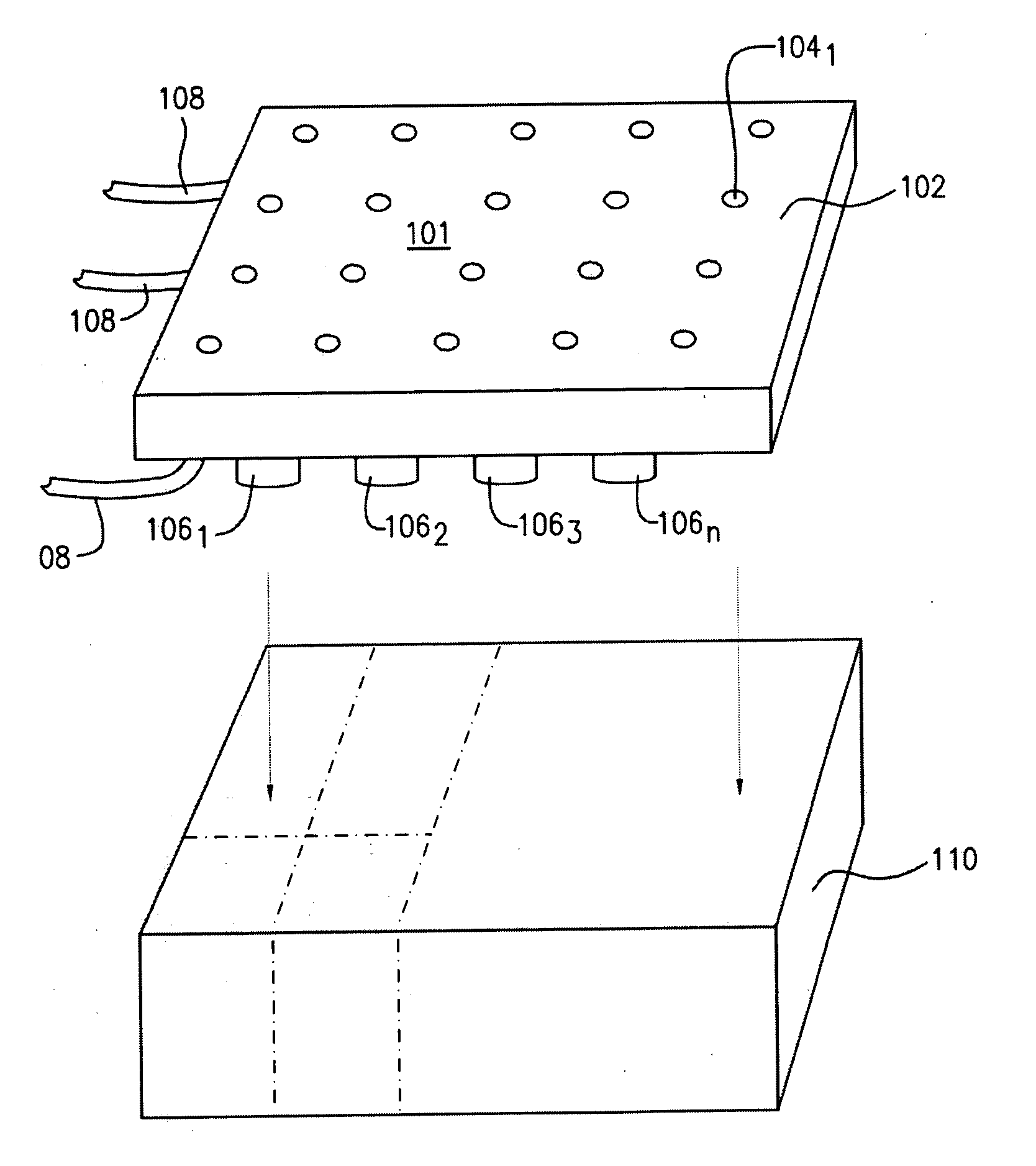
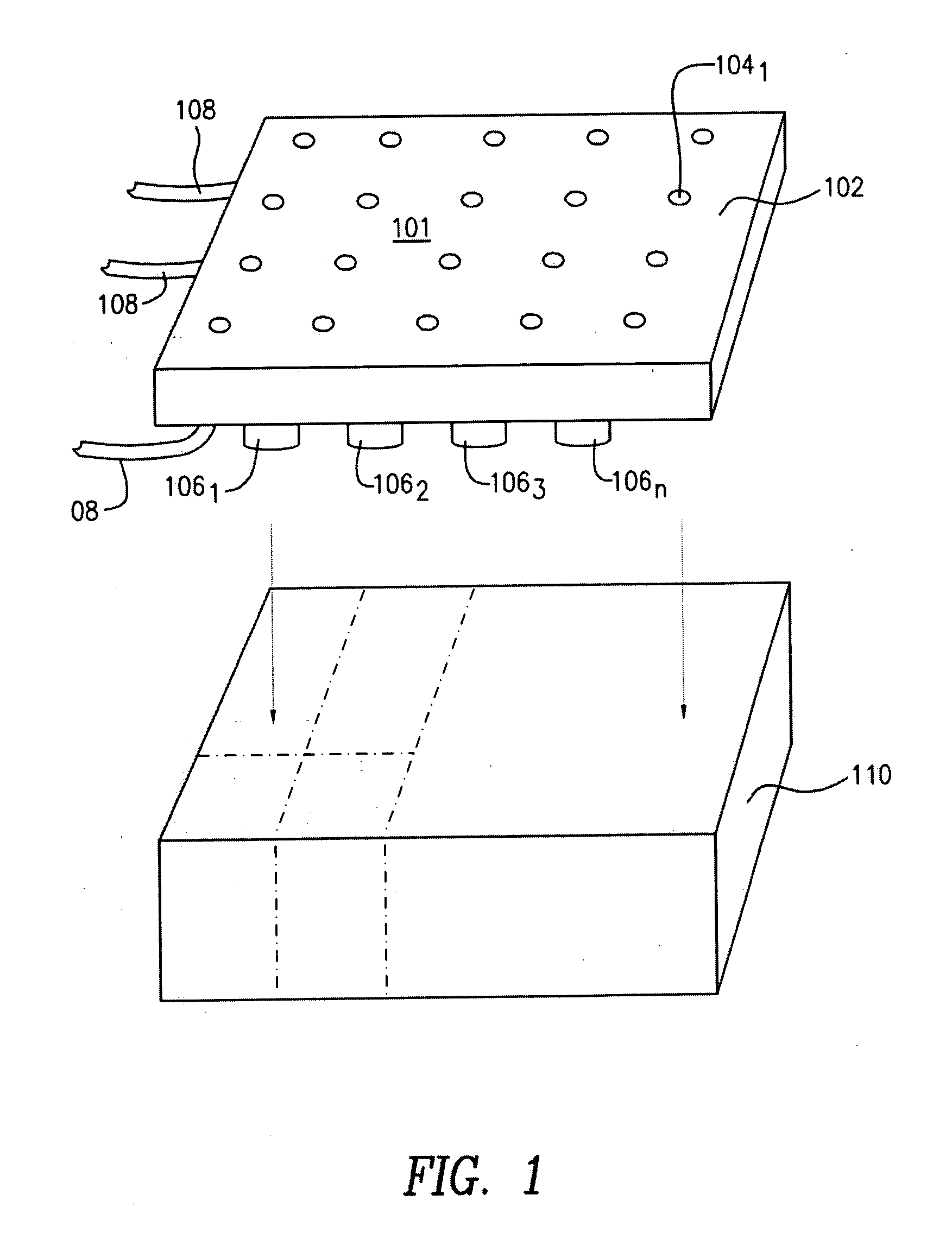
[0016]With reference to the drawings, wherein like numerals indicate like elements, there is shown in FIGS. 1-5 an air bearing assembly 100 from various viewpoints.

[0017]FIG. 1 is an exploded view of the air bearing assembly 100. The air bearing assembly 100 provides a substantially flat surface 101 from which to operate on a substrate (not shown) using an air cushion. The assembly 100 comprises an upper portion 102, a plurality of spacers 106, to 106, (collectively 106), a plurality of air / vacuum lines 108, to 108, (collectively 108), and a lower portion 110. These elements cooperate to support (e.g., float or secure in place) the substrate on a bed of air above the upper portion 102 of the assembly 100. The bed of air may be used for processes such as drying and curing of the substrate. The substrate may also be measured, cut to size, and inspected for stress fractures and other defects on the assembly. By way of example, the substrate may be a glass substrate, glass ceramic subst...


PUM

PropertyMeasurementUnit
surface areaaaaaaaaaaa
diameteraaaaaaaaaa
diameteraaaaaaaaaa

Abstract

An air bearing assembly includes: an upper portion having a plurality of air supply and vacuum holes therethrough; a lower portion; and a plurality of spacers disposed between and maintaining the upper and lower portions in spaced relation, wherein a density of the air supply and vacuum holes is high enough to provide an air bearing for a substrate, but low enough such that at least one of: (i) a sufficient number of the spacers are employed, and (ii) the spacers are located in close enough proximity, to maintain a substantially uniform flatness of the upper portion relative to the lower portion.

Description

BACKGROUND OF THE INVENTION[0001]The present invention relates to an air bearing assembly, and more specifically, an air bearing assembly used for processing or measuring flat substrates.[0002]Flat substrates, such as glass substrates, may be checked for stress deformation after cutting or any other process that may affect the quality of the substrate on an air bearing assembly. The air bearing assembly is typically a singular piece of granite having a flat upper surface. The granite is usually very thick to ensure that a solid, stable, and flat platform is obtained. Typically, it is desirable to apply air pressure (or another fluid) or to create a vacuum pressure between the substrate and the upper surface of the air bearing assembly. The vacuum pressure and air pressure is delivered by a combination of air and vacuum holes placed throughout the air bearing surface assembly. The vacuum pressure and air pressure is used to secure the substrate (e.g., for testing purposes) or to floa...

Claims


Application Information

Patent Timeline
Patent Type & Authority Applications(United States)
IPC IPC(8): G11B5/60
CPCB65G49/065B65G2249/04B65G2249/045Y10T29/49639Y10S29/044Y10T29/49998H01L21/6838B65G49/06H01L21/683
Inventor BRACKLEY, DOUGLAS E.DRUM, DAVID LEEMCCARTHY, PAUL J.
Owner CORNING INC
Learn More