
Multi-mode rain sensor

a rain sensor and multi-mode technology, applied in the field of optical rain sensors, can solve the problems of less suitable deployment approach, less aesthetically pleasing, and more expensive rain sensors, and achieve the effect of exceptional performan

Inactive Publication Date: 2008-05-22
PILKINGTON NORTH AMERICA INC
View PDF11 Cites 60 Cited by
  • Summary
  • Abstract
  • Description
  • Claims
  • Application Information

AI Technical Summary

Benefits of technology

[0020]By changing modes of operation with deployment on differing windows, the present invention allows a single rain sensor to offer exceptional performance in a wide variety of applications.

Problems solved by technology

A larger rain sensor is more costly, because of the need for more materials, and is less aesthetically pleasing.
However, the approach is less suitable when deployed on a thin windshield, as an optimal design places the emitter and detector so close together as to risk them interfering with one another.
The result is that the rain sensor either functions poorly or ceases to work at all.
A further issue with prior art rain sensors is that they are subject to misalignment.
Thus, if the optical device is misaligned, or the mounting of the rain sensor induces too much deviation to the optical path, it may be possible for a significant portion of emitter rays to miss the detector lens.
The mechanical and optical constraints of rain sensor design make it very difficult to utilize a high extent.
Most modern passenger car windshields, however, strongly absorb infrared light, rendering the multi-pass approach inoperative.

Method used


Image

  • Multi-mode rain sensor
  • Multi-mode rain sensor
  • Multi-mode rain sensor

Examples


Embodiment Construction

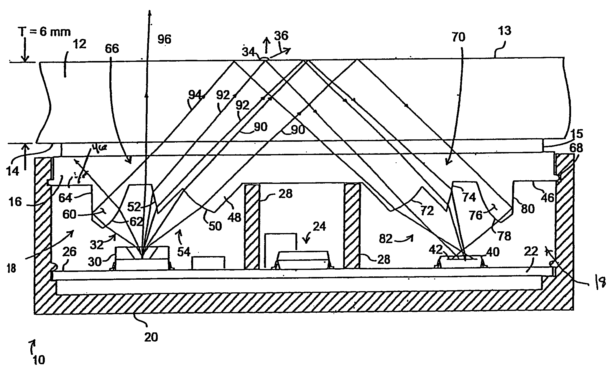
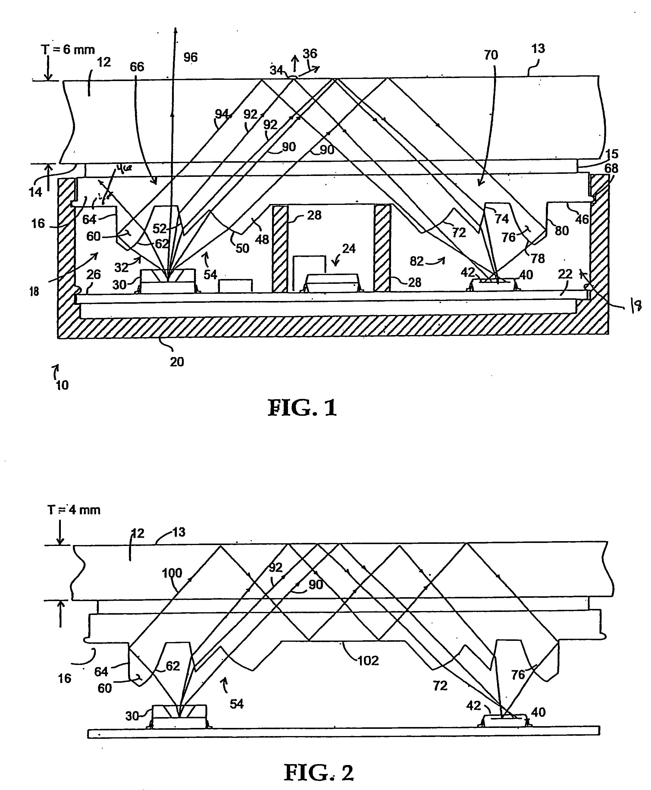
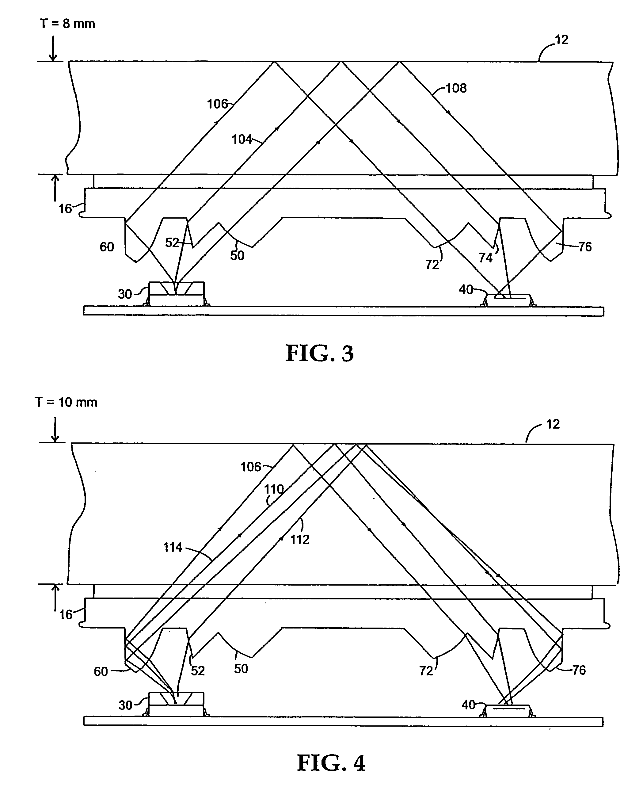
[0028]The rain sensor of the present invention allows a single rain sensor to efficiently detect the amount of moisture on vehicle windows of widely varying thickness, ranging from unusually thin windows, especially windshields, found on, for example, sports cars to exceptionally thick windows found on, for example, farm tractors. Achieving such efficiency, while keeping the physical size of the rain sensor small, and the cost of manufacturing same low, is, generally accomplished by maximizing the “extent” of the detector(s) of light rays which can then utilize a greater fraction of the light rays generated by the emitter(s). Deflection and direction of light rays by an assemblage of lenses adjacent the emitter(s) and detector(s) is also part of the present invention.

[0029]The amount of infrared (IR) energy transmittance through a window also affects the efficiency of operation of rain sensors, as earlier discussed herein. In order to account for not only variations in IR energy (or...


PUM


Abstract

The present invention relates to a rain sensor that adaptively functions in a variety of different modes when deployed on vehicle windows of different thicknesses and compositions. The arrangement of multiple lens segments and reflecting surfaces in a nonsequential configuration allows utilization of a greater proportion of light rays from the at least two emitters. Further, a greater portion of the light rays emitted by the at least two emitters is captured by the lens segments and reflectors arranged about at least two detectors, and directed to the detectors. Connection to analytical circuitry then allows interpretation of electrical signals, which in turn control, for example, window wiper systems.

Description

RELATED APPLICATION[0001]This application is claiming the benefit, under 35 U.S.C. 119(e), of the provisional application filed Nov. 16, 2006 under 35 U.S.C. 111(b), which was granted Ser. No. 60 / 859,555. This provisional application is hereby incorporated by reference in its entirety.BACKGROUND[0002]The present invention relates generally to an optical rain sensor for detecting water on an automotive window, and more particularly, to a rain sensor that is capable of operating efficiently when mounted on glass of varying thickness and composition.[0003]In recent years, it has been increasingly common for motor vehicles to incorporate optical rain sensing wiper control systems that adjust the speed of the wipers in response to the accumulation of water on the outside surface of, for example, the windshield. The rain sensors of such systems typically employ beams of light directed through the windshield at an angle of 45 degrees. The presence of rain or snow on the outside surface of ...

Claims


Application Information

Patent Timeline
IPC IPC(8): G01N21/17G06M7/00
CPCB60S1/0822G01N21/552B60S1/0837
Inventor TEDER, REIN S.
Owner PILKINGTON NORTH AMERICA INC
Learn More