System and method employing direct gasification for power generation

a technology of power generation and gasification process, applied in the direction of hot gas positive displacement engine plants, biofuels, machines/engines, etc., can solve the problems of increasing the cost of electricity by 2.5 cents to 4 cents per kwh, and thermal inefficiency in the overall gasification process

Inactive Publication Date: 2008-05-22
SIEMENS ENERGY INC
View PDF7 Cites 27 Cited by
  • Summary
  • Abstract
  • Description
  • Claims
  • Application Information

AI Technical Summary

Problems solved by technology

Removal of these materials can introduce thermal inefficiencies to the overall gasification process.
However, cost of such CO2 capture is on the order of $150 per ton of carbon and this can increase the cost of electricity by 2.5 cents to 4 cents per kWh.

Method used


Image

  • System and method employing direct gasification for power generation
  • System and method employing direct gasification for power generation
  • System and method employing direct gasification for power generation

Examples


Embodiment Construction

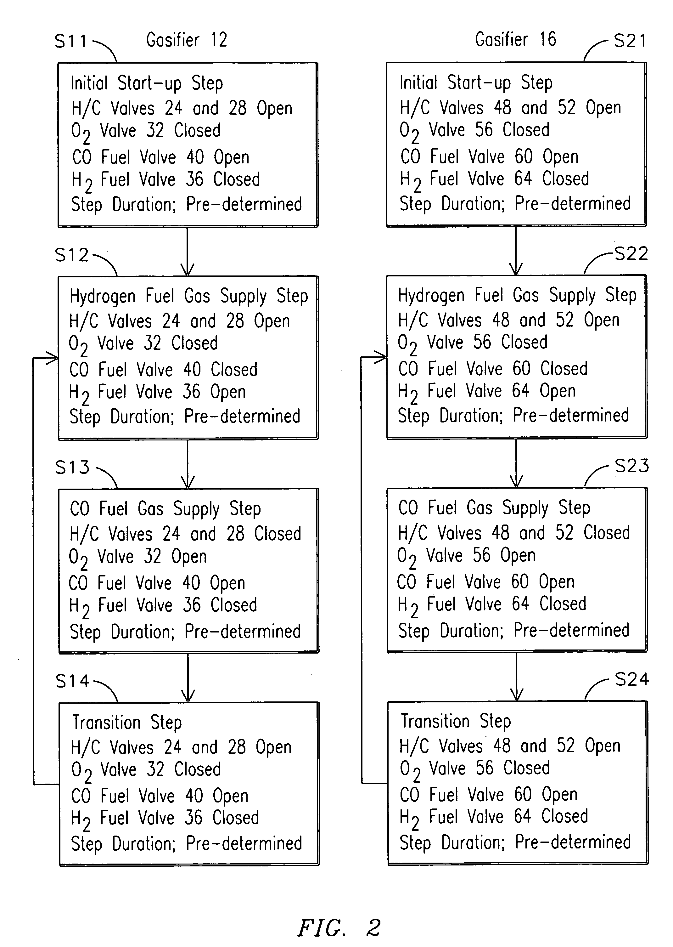
[0013]In the example embodiments now illustrated, a direct gasification process generates separate streams of H2 and CO from hydrocarbon material. The reactions take place in a melt of molten iron, although other materials, e.g., nickel, can be used in the reactor. Molten iron may be considered an ideal choice for the melt because it has a relatively high solubility for carbon.

[0014]In an exemplary process, a hydrocarbon feed is injected into the molten iron in the absence of an oxidant. The hydrocarbons breakdown, with free carbon atoms remaining dissolved in the melt. Simultaneously, as the hydrocarbons release carbon which remains in solution with the melt, hydrogen fuel gas is released from the melt. As the concentration of dissolved carbon in the melt increases, the solution, e.g., of molten iron and carbon, approaches a saturation level. At a point approaching the saturation level of carbon in the melt, the hydrocarbon feed to the melt is ceased and oxygen is injected into the...


PUM


Abstract

A power generation system (10) and method of operating a power generation system (10). An exemplary power generation system (10) shown in FIG. 1 includes a gasification system (2) for generating a supply (33) of a first gas comprising hydrogen and a supply (39) of a second gas comprising carbon monoxide based on a chemical breakdown of hydrocarbons in a melt (17). A component system (3) produces a supply of steam (99) by reacting one of the streams of gas and a steam turbine (120) generates mechanical power by expanding the steam (99). In an associated method, a melt (17) is created in a gasifier (12) which then receives a hydrocarbon source (22) to generate a continuous supply (33) of a first gas comprising hydrogen while increasing concentration of dissolved carbon in the melt (17). Hydrogen present in the first gas is supplied to a first combustor (90). A continuous supply (39) of a second gas comprising carbon monoxide is generated with carbon present in the melt (17). Carbon monoxide present in the second gas is supplied to a second combustor (80).

Description

BACKGROUND OF THE INVENTION[0001]1. Field of the Invention[0002]The present invention relates generally to power generation systems and, more particularly, to systems incorporating gasification processes.[0003]2. Background Art[0004]Integrated Gasification Combined Cycle (IGCC) systems present an opportunity to deploy coal, an abundant resource, in an economical and clean manner, bringing improved efficiency and cost over conventional coal-burning steam turbine power generation systems as well as Natural Gas Combined Cycle (NGCC) systems. In an IGCC system, a carbonaceous fuel such as coal, or heavy oil, or petroleum coke is converted to a gaseous fuel, termed syngas, a mixture formed by partial oxidation at elevated temperatures. Components of syngas vary considerably depending on the fuel source and reaction conditions. For coal gasification with compressed oxygen, typical constituents of syngas include H2, CO, CO2, and CH4. In addition, syngas normally includes impurities such as...

Claims


Application Information

Patent Timeline
Patent Type & Authority Applications(United States)
IPC IPC(8): F02C3/26
CPCF02C3/28Y02E50/12Y02E20/18Y02E50/10
Inventor RISING, BRUCE
Owner SIEMENS ENERGY INC
Why Eureka
Try Eureka