
Assembly element including two superposed strip shaped elastic structures and timepiece fitted with the same

a technology of elastic structure and assembly element, which is applied in the field of assembly element and timepiece, can solve the problems of not being able to drive a hollow cylinder onto a conventional rotating arbour, and achieve the effects of improving gripping force, better stress distribution, and better control of gripping for

Active Publication Date: 2008-05-15
ETA SA MFG HORLOGERE SUISSE
View PDF9 Cites 14 Cited by
  • Summary
  • Abstract
  • Description
  • Claims
  • Application Information

AI Technical Summary

Benefits of technology

[0009]The assembly element according to the invention improves the gripping force against the arbour, to allow better distribution of the stress linked to the elastic deformation in the material forming the assembly element, and to allow better control of the gripping force obtained on the arbour. In particular, the return forces of each elastic strip of a stack are added together while maintaining the lowest possible level of stiffness for each elastic strip. Significant flexion of the elastic structure is obtained, in particular on the support surface, without departing from the elastic range of the material. Thus, the elastic structures according to the invention offer sufficiently large radial clearance, after their elastic deformation, to compensate for the manufacturing tolerances applied to the diameter of an arbour like those used for driving hands in timepieces.
[0017]the support surface of the first elastic strip includes discrete raised elements which increase the friction between the arbour and the support surface;

Problems solved by technology

For components made of a brittle material such as silicon, which does not have a usable plastic range, it is not possible to drive a hollow cylinder onto a conventional rotating arbour like those used in mechanical watchmaking, with a diameter tolerance of the order of + / −5 microns.

Method used


Image

  • Assembly element including two superposed strip shaped elastic structures and timepiece fitted with the same
  • Assembly element including two superposed strip shaped elastic structures and timepiece fitted with the same
  • Assembly element including two superposed strip shaped elastic structures and timepiece fitted with the same

Examples


Embodiment Construction

[0031]In the following description, identical or similar elements will be designated by the same reference numerals.

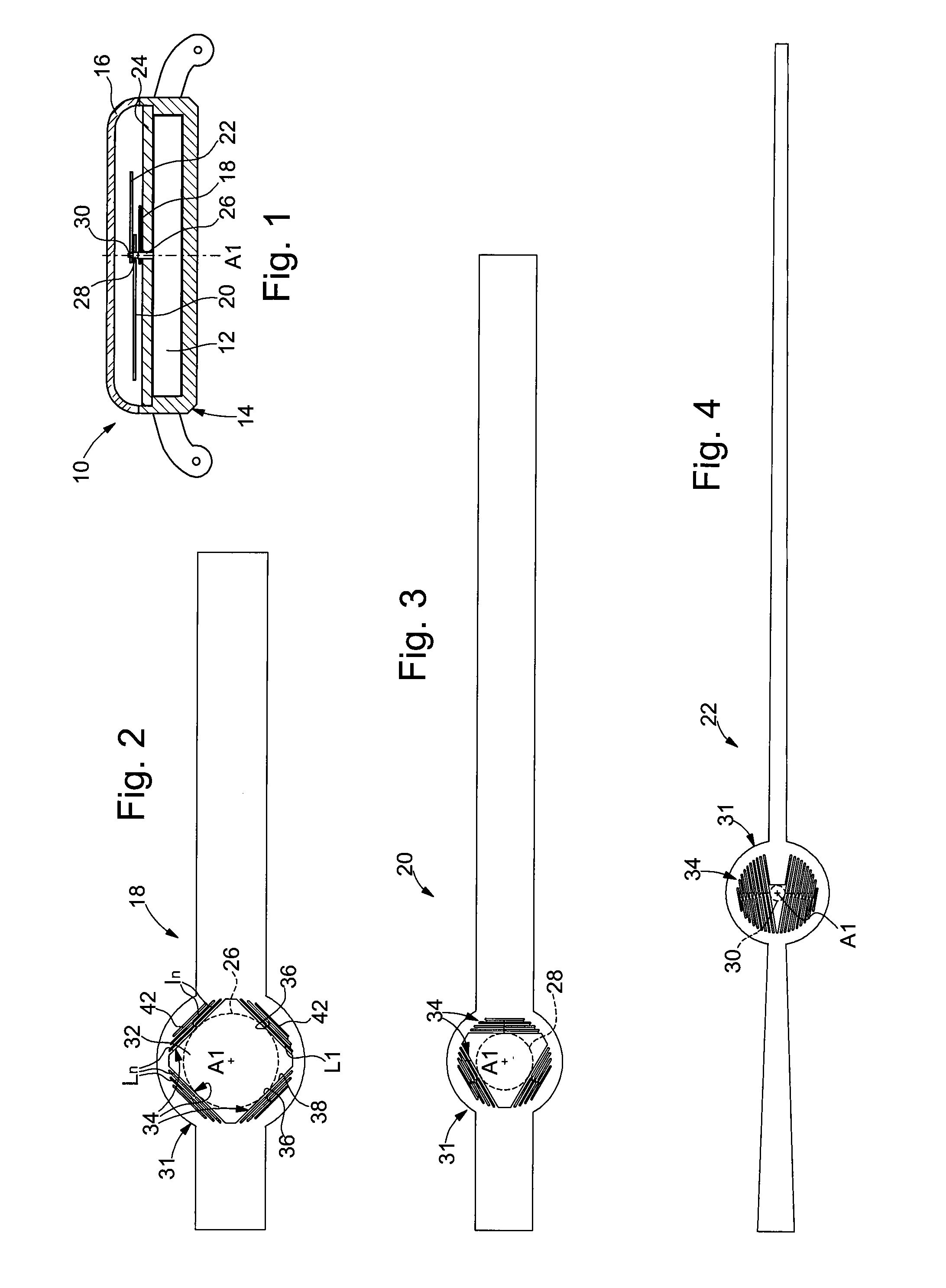
[0032]FIG. 1 shows schematically a timepiece 10 which is made in accordance with the teaching of the invention.

[0033]Timepiece 10 includes a movement 12 mounted inside a case 14 closed by a crystal 16. Movement 12 drives in rotation, about an axis A1, analogue display means formed here by an hour hand 18, a minute hand 20 and a second hand 22, these hands extending above a dial 24. Hands 18, 20, 22 are secured by being elastic gripped to coaxial cylindrical rotating arbours 26, 28, 30, in a driving in type arrangement, as will be seen hereafter.

[0034]Preferably, arbours 26, 28, 30 are conventional arbours commonly used in timepiece movements, for example metal or plastic arbours.

[0035]In the following description, we will use in a non-limiting manner, an axial orientation along rotational axis A1 of hands 18, 20, 22 and a radial orientation relative to axis A1. Moreove...


PUM


Abstract

Assembly element (18) made in a plate of brittle material, including an aperture (32) provided for the axial insertion of an arbour (26), the inner wall (33) of the aperture (32) including elastic structures (34), which are etched into the plate to grip the arbour (26) radially. Each elastic structure (34) includes a first rectilinear elastic strip (L1) which extends along a tangential direction relative to the arbour (26). According to the invention, each elastic structure (34) is formed by a radial stack of several parallel elastic strips.The invention also proposes a timepiece fitted with this assembly element (18).

Description

[0001]This application claims priority from European Patent Application No. 06123784.8 filed 9 Nov. 2006, the entire disclosure of which is incorporated herein by reference.BACKGROUND OF THE INVENTION[0002]The invention concerns an assembly element and a timepiece comprising the same.[0003]The invention concerns more specifically an assembly element made in a plate of brittle material such as silicon, particularly for a timepiece, including an aperture provided for the axial insertion of an arbour, the inner wall of the aperture including elastic structures which are etched in the plate and which each comprise at least one support surface for gripping or squeezing the arbour radially in order to secure the assembly element relative to the arbour, wherein each elastic structure includes a first rectilinear elastic strip which extends along a tangential direction relative to the arbour, the support surface being arranged on the inner face of the first elastic strip.[0004]Generally, in...

Claims


Application Information

Patent Timeline
IPC IPC(8): B32B3/10
CPCG04B13/026G04B19/042Y10T74/19Y10T428/24273G04D3/0046G04B13/021G04B17/06G04B17/00
Inventor BITTERLI, ROLANDNOELL, WILFRIEDBLONDEAU, FABIENPARATTE, LIONELSCHARF, TORALFMEISTER, PIERRE-ANDREZANETTA, ANDRE
Owner ETA SA MFG HORLOGERE SUISSE
Learn More