
Dispersion Devices For Aggregates

a technology of aggregates and dispersion devices, which is applied in the direction of gas current separation, grain treatment, biomass after-treatment, etc., can solve the problems of increasing the production of viable cells, reducing the yield of biomass production and compounds of interest, and forming cell aggregates during the cultur

Active Publication Date: 2008-05-08
MERIAL INC
View PDF9 Cites 17 Cited by
  • Summary
  • Abstract
  • Description
  • Claims
  • Application Information

AI Technical Summary

Benefits of technology

[0019] The present invention further provides a flow-through method for dispersion of aggregates, comprising the steps of (1) flowing of a suspension containing cell aggregates through a dispersion device according to the invention, thereby disrupting t...

Problems solved by technology

Firstly, cell amplification by subculture will result in increases in biomass production of viable cells.
A major problem of the cell culture is the formation of cell aggregates formed during the culture.
Cell aggregates, by limiting access of the cells to nutrients and by contact growth inhibition, reduces the culture yield in terms of biomass production and of compounds of interest.
In addition, cell aggregation increases cell death, primarily due to apoptosis.
Cultures of anchorage-independent cells also exhibit cell clusters, and that the problem of cell cluster dispersion exists, irrespective of what type of anchorage the cells have.
Dispersion of cells can be a solution to the inherent problems of cell aggregation but is also problematic, however, due to the fragility of cells resulting in stresses and deaths.
All of these treatments are usually insufficient individually to obtain a uniformly dispersal of viable individual cells.
These steps are time consuming and increase the cost of the product and may result in undesirable reaggregation.
Compared to microorganisms such as viruses and bacteria, eukaryotic cells, and especially animal cells, are very fragile and shear sensitive due to the lack of a durable cell wall.
In mouse and human cell culture experiments, wall shear stresses of 100 N / m2 over 0.5 seconds residence time cause a significant cell death rate.
As a general consideration, therefore, shear forces applied on a cell suspension could result in a decrease in cell viability.
Shearing forces may decrease the yield of the viable cells and can also reduce the ability of the cells to divide by inhibition of cell mitosis.
This manual operation is not, however, consistent and reproducible.
In addition, shear damage is a function of both shearing time and shearing forces.
Pipetting too vigorous and / or over too long a period can damage the cells and result in low viability.
Alternatively, pipetting too gently or inconsistently and difficulty of determining when cell clusters have disappeared can result in a poor cell yield because remaining cell aggregates will be discarded during subsequent filtration steps.
Beside this lack of robustness, the gentle pipetting technique is tedious and requires open phases that increase the risks of contamination.
Pipetting is not amenable to large volume processing.

Method used


Image

  • Dispersion Devices For Aggregates
  • Dispersion Devices For Aggregates
  • Dispersion Devices For Aggregates

Examples


example 1

[0069] The preparation, propagation and infection of chicken embryo cells with Marek disease virus (MDV) were performed in 1700 cm2 rolling bottles. Infected chicken embryo cells of all the rolling bottles were dissociated by trypsination after attaining 50 to 70% CPE (cytopathic effect), then harvested by centrifugation at 500 g during 12 minutes.

[0070] After centrifugation, the supernatant was removed and freezing media was added to the pellet to obtain a cell suspension, but which contained many aggregates clearly visible to the naked eye.

[0071] For the dispersion of aggregates, two methods were used. In a first method, the cell suspension from 406 rolling bottles was homogenized by manual pipetting with a 50 ml pipette. The resulting suspension was extemporaneously filtered on a 800 μm Nylon bag, adjusted in volume with some freezing media then analyzed.

[0072] In parallel, the cell suspension equivalent of 48 rolling bottles was processed 8 times consecutively through a flow-...

example 2

[0080] Preparation, propagation and infection of chicken embryo cells with Marek disease virus (MDV) were performed in 1700 cm2 rolling bottles. Infected chicken embryo cells of all the rolling bottles were dissociated by trypsination after completion of 50 to 70% CPE (cytopathic effect), then harvested by centrifugation at 500 g during 10 minutes. Around 2300 rolling bottles were processed.

[0081] After centrifugation, the supernatant was removed and freezing media was added to the centrifugation bucket containing the pellet. The bucket was swirled by hand to obtain a coarse cell suspension, but which still contained many aggregates visible to the naked eye. The cell suspension was stirred during 10 minutes and divided equally into six containers.

[0082] One container was processed as a standard without cell splitting. The cell suspension was directly filtered on a cheese-cloth. The filtrate was furthermore diluted with freezing media before filling.

[0083] The five remaining conta...


PUM


Abstract

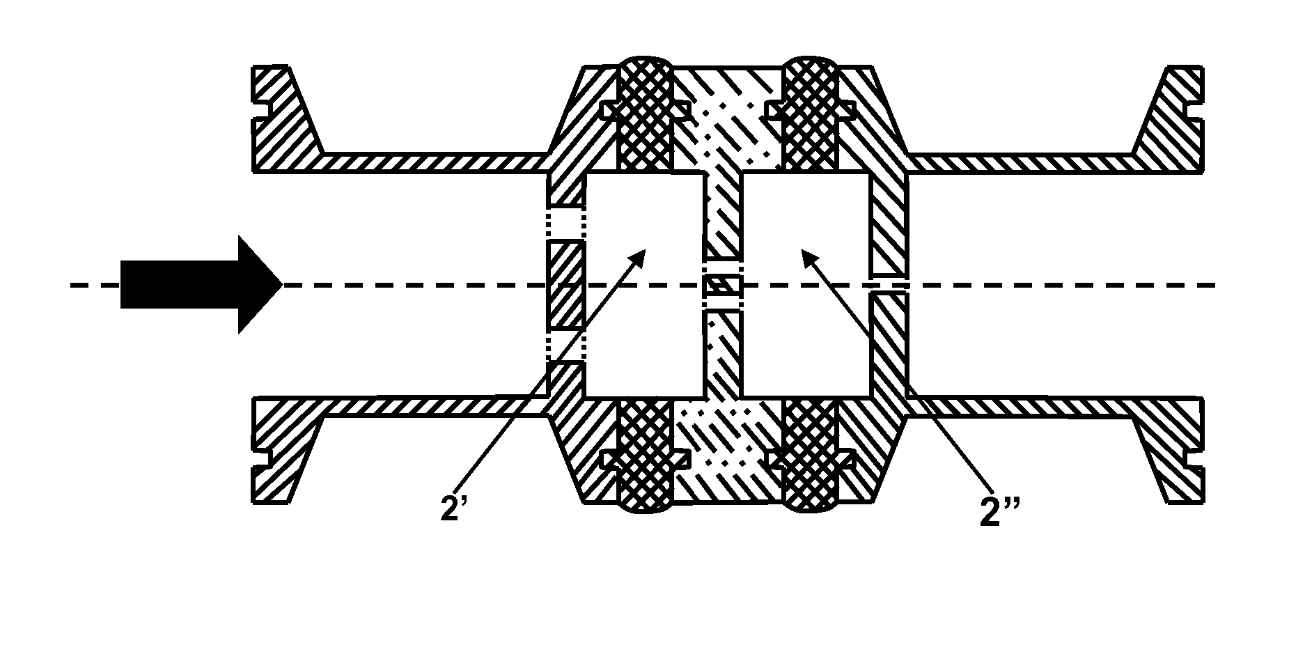
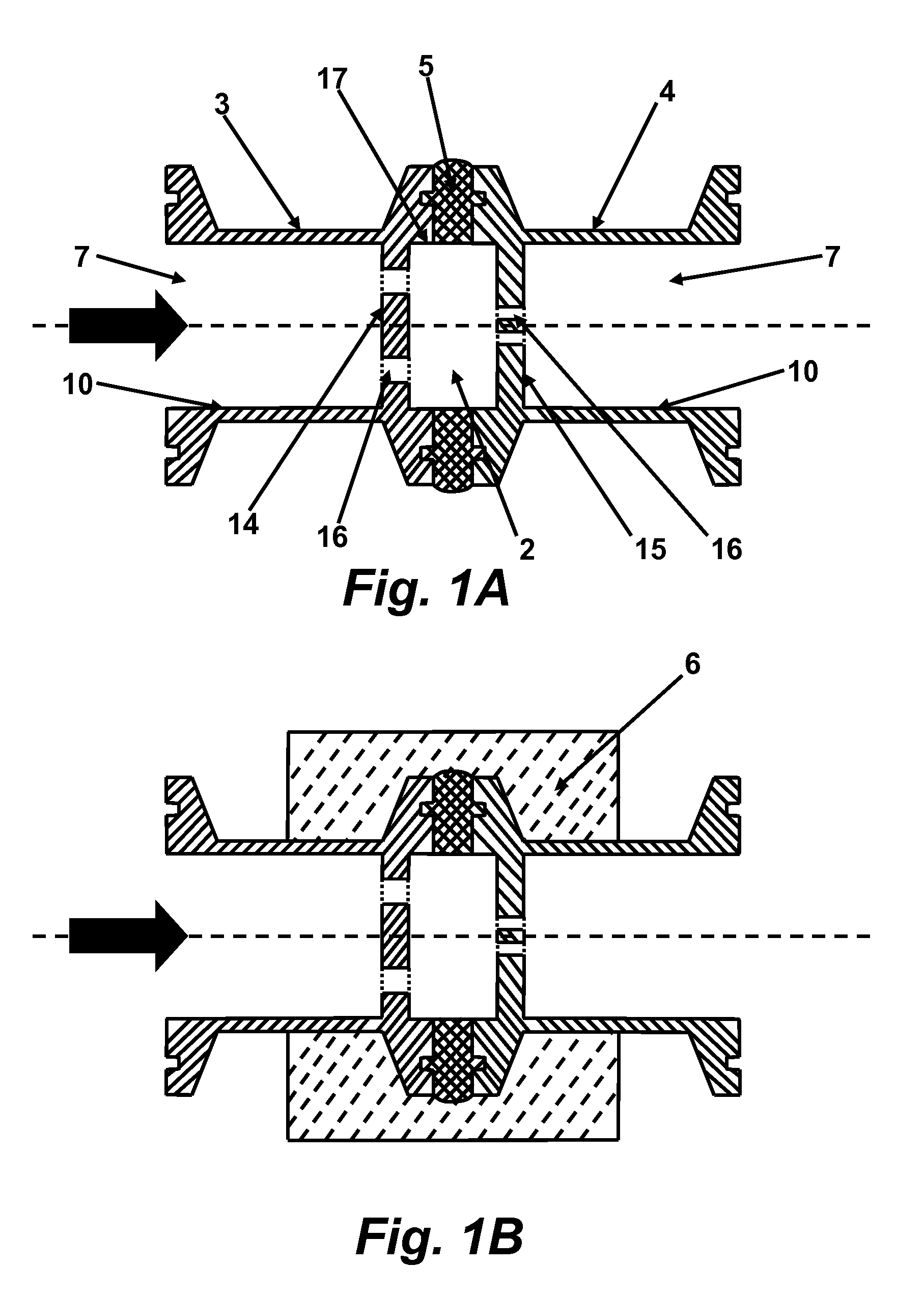
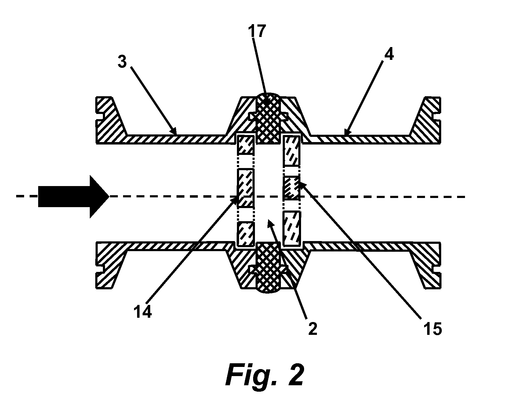
The present invention encompasses a flow-through dispersion device for the dispersion of cell aggregates, the device comprising a first or upstream inlet obstacle and a second or downstream outlet obstacle, each obstacle having at least one traversing hole wherein no two holes align. Between the two obstacles is a turbulence chamber, such that when a cell suspension is passed through the inlet holes, into the chamber and then exits the second obstacle, the turbulence within the chamber disrupts and disperses cell aggregates. The device optionally may have more than two obstacles and turbulence chambers and multiple units may be placed in series to increase the amount of turbulence and time applied to a volume of cells. The invention further encompasses methods of using the device to disperse cell aggregates, and methods of culturing cells that involve seeding cultures and maintaining dispersed individual cells.

Description

FIELD OF THE INVENTION [0001] The present invention relates to flow-through dispersion devices for dispersion of aggregates, especially of culture suspensions containing cell aggregates. The present invention provides flow-through methods for dispersing aggregates to release individual cells. The present invention further relates to flow-through methods for homogenization of animal cells suspensions containing cell aggregates. BACKGROUND OF THE INVENTION [0002] During the past 100 years, cell cultures have resulted in many applications in the field of biotechnology. Progress in cell culture, especially in obtaining higher cell productivity, has allowed the development of new processes for production of recombinant proteins and vaccines, biomass and new uses of cells such as cell therapies. [0003] Cells are mainly cultured for two applications. Firstly, cell amplification by subculture will result in increases in biomass production of viable cells. These viable cells can be used for ...

Claims


Application Information

Patent Timeline
IPC IPC(8): C12M1/00C12N5/06C12N5/073
CPCC12M43/02C12N2531/00C12N5/0603C12M47/06
Inventor RIGAUT, GUILLAUME
Owner MERIAL INC
Learn More