Eureka AIR delivers breakthrough ideas for toughest innovation challenges, trusted by R&D personnel around the world.

Network Configuring Method, Network System and Relay Apparatus

a network and relay technology, applied in electrical devices, digital transmission, data switching networks, etc., can solve problems such as increased costs, and achieve the effect of reducing system downtime due to configuration change of network or relay apparatuses and low cos

Inactive Publication Date: 2008-05-08
FUJITSU LTD
View PDF4 Cites 13 Cited by
  • Summary
  • Abstract
  • Description
  • Claims
  • Application Information

AI Technical Summary

Benefits of technology

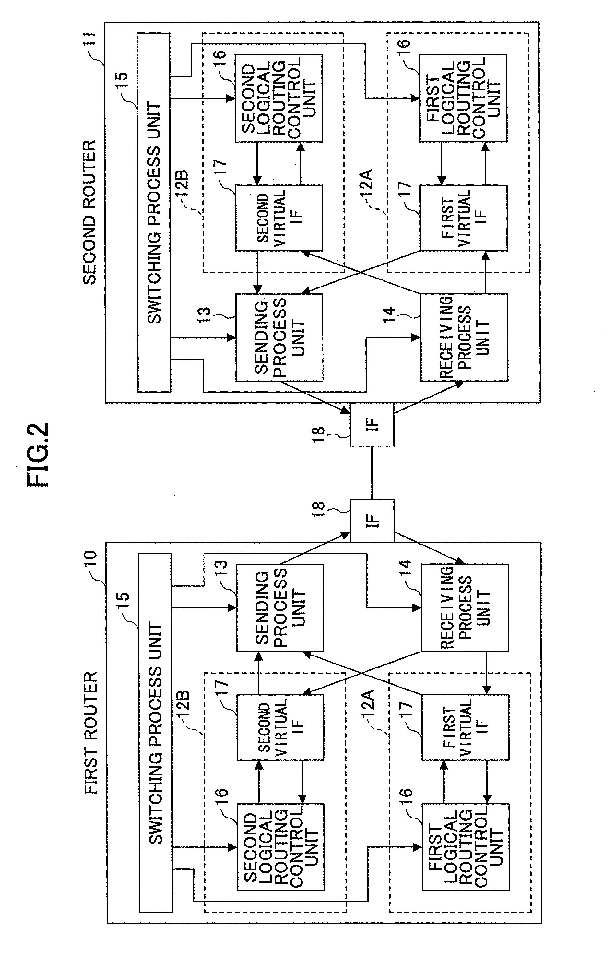
The present invention provides a network configuring method, system, and relay apparatus that can be realized with low cost and minimize system downtime due to configuration change of a network. The relay apparatus includes a first logical relay unit, a second logical relay unit, a protocol assignment unit, a sending unit, a receiving unit, and a switching process unit. The relay apparatus can switch between the first and second logical relay units based on a protocol identifier in a packet header. This allows for seamless switching between the two logical relay units and ensures continuous network communication.

Problems solved by technology

However, in the method for introducing redundancy by providing a current system and a standby system that are physically independent, there is a problem in that cost is increased since relay apparatuses are prepared for each network.

Method used


Image

  • Network Configuring Method, Network System and Relay Apparatus
  • Network Configuring Method, Network System and Relay Apparatus
  • Network Configuring Method, Network System and Relay Apparatus

Examples


first embodiment

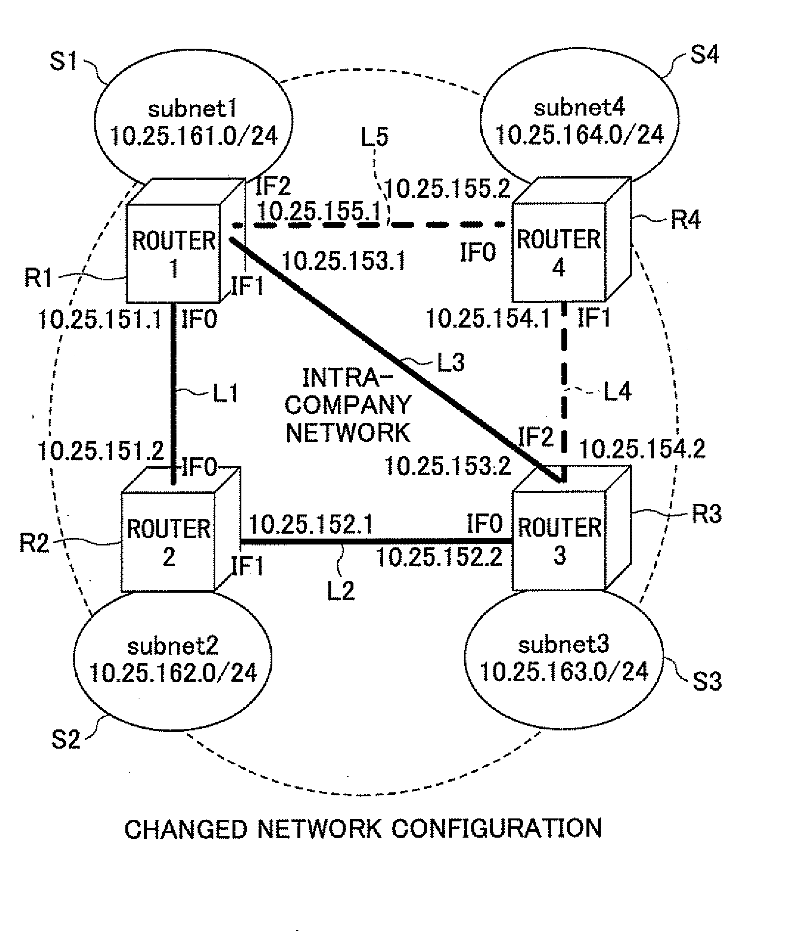
[0089]FIG. 3A shows a block diagram of a current network according to the first embodiment of the present invention. FIG. 3B is a block diagram of a network to be realized by changing the network shown in FIG. 3A.

[0090]FIG. 3A shows an intra-company network for example. The network includes three routers R1, R2 and R3 having subnetworks S1, S2 and S3 respectively under the routers. The router R1 has a subnetwork S1 to which a network address 10.25.161.0 / 24 is assigned.

[0091] The router R2 has a subnetwork S2 to which a network address 10.25.162.0 / 24 is assigned. In the same way, the router R3 has a subnetwork S3 to which a network address 10.25.163.0 / 24 is assigned. The routers are interconnected by links L1-L3 that are gigabit Ethernet links.

[0092] The router R1 and the router R2 are interconnected by the link L1 to which a network address 10.25.151.0 / 24 is assigned, and an address 10.25.151.1 is assigned to an interface IF0 of the router R1. An address 10.25.151.2 is assigned t...

second embodiment

[0158] Also in the second embodiment, like the first embodiment, the network configuration is changed from current one shown in FIG. 3A to another one shown in FIG. 3B.

[0159]FIG. 37 is a flowchart showing system operation of the second embodiment of the present invention.

[0160]

[0161] A network manager prepares a current network shown in FIG. 3A using router apparatuses of the present invention beforehand.

[0162] In the protocol assignment table 28 of each router, as default values as shown in FIG. 38, “value other than 254” is set as a protocol value of the logical router 22A, and “254” is set as a protocol value for the logical router 22B. In the present embodiment, the logical router 22A adds an Ether header to an IP packet to send a MAC frame shown in FIG. 14. The logical router encapsulates an IP packet by adding an Outer IP header (protocol layer header) and further adds an Ether header to send a MAC frame (refer to after-mentioned FIG. 46). Then, the above-mentioned protocol...


PUM


Abstract

A relay apparatus for performing relay possessing is disclosed. The relay apparatus includes a first logical relay unit; a second logical relay unit; a sending unit configured to add a packet header including a first protocol identifier or a second protocol identifier registered in a protocol assignment unit to a packet to be sent by the first logical relay unit or the second logical relay unit, and to send the packet to a network; a receiving unit configured to pass a received packet to the first logical relay unit or the second logical relay unit by referring to the protocol assignment unit based on a protocol identifier in a packet header of the received packet; and a switching process unit configured to change correspondence relationship for the first and the second protocol identifiers to switch between the first logical relay unit and the second logical relay unit.

Description

BACKGROUND OF THE INVENTION [0001] 1. Field of the Invention [0002] The present invention relates to a network configuring method, a network system and a relay apparatus. [0003] 2. Description of the Related Art [0004] Today, service provider networks and intra-company networks are required to continue operation for 24-hours in 365 days a year. However, in these networks, configuration change for relay apparatuses often occurs due to change of operation policy of the networks, addition of new subnetworks and the like. [0005] If network service must be stopped until finishing verification of new configuration, complicated configuration change may make service downtime become long. In order to decrease such a state in which users cannot perform network communication as much as possible, a mechanism is necessary for updating network configuration while minimizing system downtime. [0006] For minimizing the system downtime, like a network system shown in FIG. 1, redundancy is introduced ...

Claims


Application Information

Patent Timeline
Patent Type & Authority Applications(United States)
IPC IPC(8): H04L12/56H04L45/02H04L45/243
CPCH04L12/2697H04L41/0803H04L43/50H04L45/02H04L45/50H04L45/28H04L45/586H04L12/4641H04L12/5689H04L45/22H04L45/00
Inventor OGUCHI, NAOKI
Owner FUJITSU LTD
Why Eureka
Eureka Blog
Learn More