
Device for launching unmanned missiles from an aircraft

a technology for unmanned missiles and aircraft, which is applied in the direction of aircraft, unmanned aerial vehicles, vehicles, etc., can solve the problem of reducing the total load of unmanned missiles transported in the transport aircraft, and achieve the effect of low net weigh

Active Publication Date: 2008-05-08
MBDA DEUTSCHLAND GMBH
View PDF9 Cites 14 Cited by
  • Summary
  • Abstract
  • Description
  • Claims
  • Application Information

AI Technical Summary

Benefits of technology

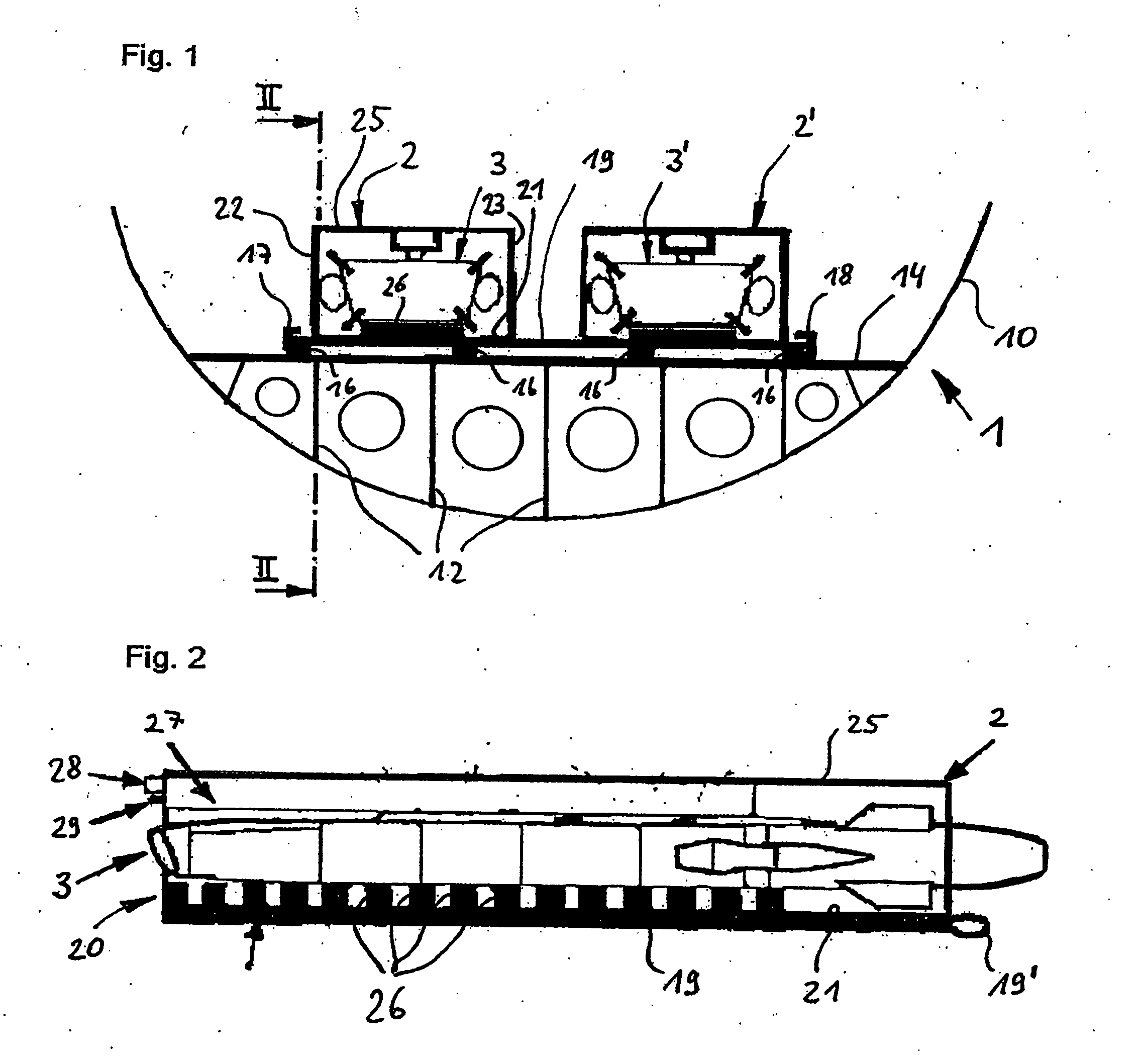
[0011]The present invention is directed to a device that makes it possible, with a low net weight, to launch several missiles from an aircraft simultaneously. This is attained with a device for launching unmanned missiles from an aircraft with a pallet, on which at least one container is provided to receive a missile. The container has an upper container section that has a pylori for the suspended, detachable support of the missile. The container also has a lower container section that is embodied as a support area for the missile.
[0012]The pylori holding the missile in the upper container section and the support area for the missile in the lower container section makes it possible to support the major load of the missile directly on the cargo hold floor of the aircraft, via the support area in the lower container section. This arrangement also makes it possible to provide a defined support of the unmanned missile on the pylori in the upper container area in which electric connections between the parent aircraft and the unmanned missile and corresponding release mechanisms to release the unmanned missile are provided.
[0016]In embodiments, it is preferred that the release mechanism for opening the holder of the missile is provided on the pylori. The release mechanism preferably has at least one propellant gas cylinder, which causes the holder of the missile to open, and an ignition device for the propellant gas cylinder. To increase safety, it is preferred that the ignition device be secured against accidental ignition by use of a securing device that has a securing pin provided on the pylori. The ignition device has a delay device, e.g., a hardware timer, which causes the ignition device to be unlocked only after a preset delay period has elapsed after the release of the securing device. This ensures that the pallet can first move away from the aircraft before the ignition device is unlocked.

Problems solved by technology

However, such a large weight results in the total load of the unmanned missiles transported in a transport aircraft having to be reduced, which is undesirable.

Method used


Image

  • Device for launching unmanned missiles from an aircraft
  • Device for launching unmanned missiles from an aircraft
  • Device for launching unmanned missiles from an aircraft

Examples


Embodiment Construction

[0028]The particulars shown herein are by way of example and for purposes of illustrative discussion of the embodiments of the present invention only and are presented in the cause of providing what is believed to be the most useful and readily understood description of the principles and conceptual aspects of the present invention. In this regard, no attempt is made to show structural details of the present invention in more detail than is necessary for the fundamental understanding of the present invention, the description taken with the drawings making apparent to those skilled in the art how the several forms of the present invention may be embodied in practice. Reference numbers in the specification and the drawings serve only to better clarify the invention and are not intended to restrict the scope of protection.

[0029]FIG. 1 shows a diagrammatic representation of a fuselage 10 of an aircraft 1 that is used as a transport aircraft for launching unmanned missiles. A loading flo...


PUM


Abstract

A device for launching unmanned missiles from an aircraft with a pallet, on which at least one container is provided to receive a missile. The container has an upper container section that has a pylori for the suspended, detachable support of the missile. The container has a lower container section that is embodied as a support area for the missile.

Description

CROSS-REFERENCE TO RELATED APPLICATIONS[0001]The present application claims priority under 35 U.S.C. § 119 of German Patent Application No. 10 2006 029 147.6, filed on Jun. 24, 2006, the disclosure of which is expressly incorporated by reference herein in its entirety.BACKGROUND OF THE INVENTION[0002]1. Field of the Invention[0003]The present invention relates to a device for launching unmanned missiles from an aircraft with a pallet, on which at least one container is provided to receive the missile.[0004]2. Discussion of Background Information[0005]Launching unmanned missiles from an aircraft, in particular from a transport aircraft, is referred to as an “airdrop.” Unmanned missiles are ejected from the aircraft during flight through an opened tailgate, at which time the missiles autonomously begin their own flight mission. Unmanned missiles of this type can be, e.g., cruise missiles or reconnaissance drones.[0006]A generic device is known, e.g., from DE 103 38 963 A1. In this gen...

Claims


Application Information

Patent Timeline
Patent Type & Authority Applications(United States)
IPC IPC(8): B64D1/12
CPCB64C2201/206B64D1/12B64U80/82
Inventor GRABMEIER, MICHAEL
Owner MBDA DEUTSCHLAND GMBH
Learn More