Eureka AIR delivers breakthrough ideas for toughest innovation challenges, trusted by R&D personnel around the world.

Foldable Intravascularly Inserted Blood Pump

a blood pump and foldable technology, applied in the field of foldable intravascularly insertable blood pumps, can solve the problems of difficult to meet the requirements of a foldable blood pump, and achieve the effects of reducing susceptibility to failure, and facilitating us

Active Publication Date: 2008-05-01
ABIOMED EURO
View PDF5 Cites 230 Cited by
  • Summary
  • Abstract
  • Description
  • Claims
  • Application Information

AI Technical Summary

Benefits of technology

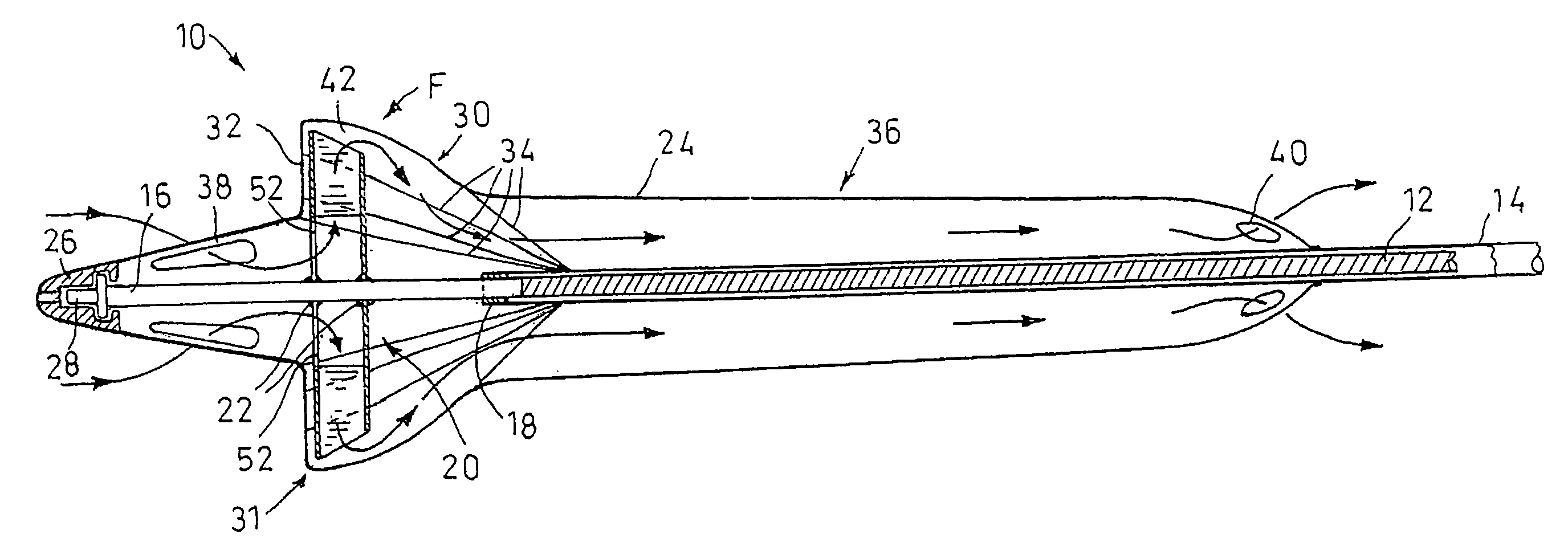
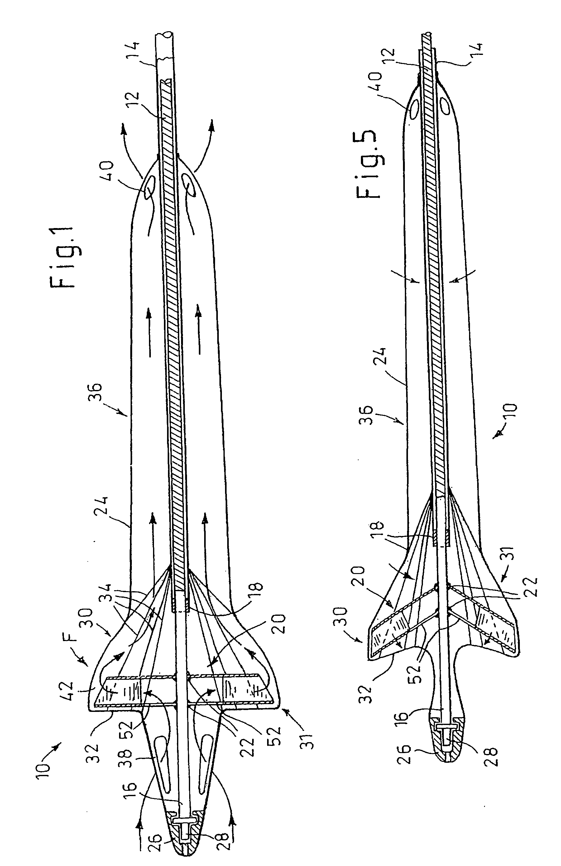
[0006]It is an object of the invention to provide a foldable intravascularly insertable blood pump of simplified configuration and reduced susceptibility to failure. According to the invention, the rotor is a radially delivering impeller. The envelope comprises an annular bulge in the impeller region, wherein between the radially outer ends of the vanes and the envelope an annular deflection channel is defined which deflects the radial blood flow in axial direction. The blood pump according to the invention is a centrifugal pump, wherein the impeller accelerates the liquid in a radial outward direction without any essential axial component. Such a centrifugal pump does not require close tolerances between the impeller and the envelope. The axial alignment of the flow is produced by deflection. The blood pump is unsusceptible to misalignments and allows for large tolerances, which is of great importance in particular in a foldable pump. A radially delivering impeller requires a relatively low speed of approximately 5,000 to 15,000 rpm for radially delivering a typical amount of blood of approximately 2 to 5 l / min. The technical setup of the radial pump is simple.
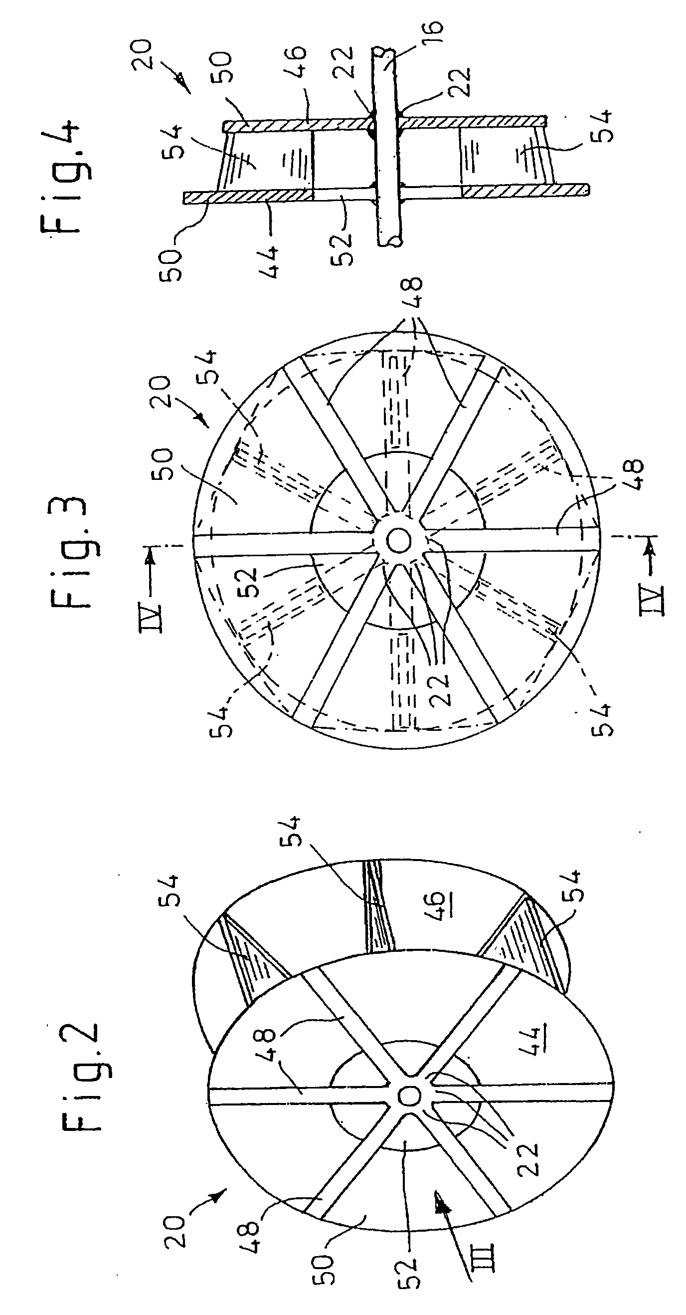
[0008]The impeller may comprise two essentially parallel supporting walls between which flexible sails are provided as vanes. This offers a technically simple configuration of a foldable impeller and thus the required stability when the impeller rotates for the purpose of delivering blood. For further increasing the stability, at least one of the supporting walls may be provided with spokes. The spokes may be radially arranged and, together with the impeller, are adapted to be folded against the shaft.
[0009]One supporting wall may be of continuous configuration, i.e. extending radially continuously from the shaft to the radially outer end of the supporting wall, and the other supporting wall may comprise an opening enclosing the shaft. The continuous supporting wall is preferably the rear supporting wall as seen in the direction of blood flow, and the supporting wall comprising the opening is preferably the front supporting wall as seen in the direction of blood flow. The blood may flow in though the supporting wall comprising the opening, and is then deflected towards the vanes by the continuous supporting wall. This allows a simple manner of deflecting an axial blood flow for the purpose of radial delivery.
[0010]The supporting walls may be fastened to the shaft by hinges. This allows the supporting walls to be folded against the shaft for reducing the outer diameter of the blood pump, for example for intravascular insertion of the pump. The effect of the centrifugal force produced during rotation of the shaft lends to the impeller the stability required for blood delivery.
[0012]Both supporting walls may comprise congruent spokes. The spokes preferably define spoke wheels, wherein between the respective congruent spokes of the two spoke wheels flexible sails may be arranged. The sails extend through the congruent arrangement of the spokes and perpendicularly to the plane of the spoke wheel. This arrangement allows for a simple technical setup of the impeller. At the front end the shaft may comprise a rigid portion to which the impeller is fastened for increasing the dimensional stability of the blood pump.

Problems solved by technology

These requirements are difficult to fulfill with a foldable blood pump.

Method used


Image

  • Foldable Intravascularly Inserted Blood Pump
  • Foldable Intravascularly Inserted Blood Pump
  • Foldable Intravascularly Inserted Blood Pump

Examples


Embodiment Construction

[0029]The blood pump 10 comprises an elongate flexible bendable shaft 12 included in a catheter 14. The catheter 14 is defined by a flexible tube with a diameter of approximately 2 mm. The catheter 14 is preferably made of an abrasion-resistant polymer, such as polyamide or polyurethane. The flexible shaft 12 extends through the catheter 14. The shaft is conventionally defined by a multi-file wire bundle and can be made hollow for accepting a central guide wire 56, if desired. Shaft 12 is driven at its proximal end by a motor not shown, e.g. at 5,000 to 15,000 rpm, while the catheter 14 is retained in place. At the distal end, i.e. the left end in FIG. 1, the shaft 12 comprises a rigid portion 16. The distal end of the catheter 14 is connected with the shaft via a sliding bearing 18. An impeller 20 is fastened to the rigid portion 16 of the shaft 12 via hinges 22 such that the impeller is foldable against the shaft 12. The impeller 20 and a distal portion of the shaft 12 and the cat...


PUM


Abstract

A foldable intravascularly insertable blood pump comprises a rotatable impeller provided with vanes, a flexible shaft extending through a catheter and adapted to drive said impeller, and an envelope enclosing said impeller. For simplifying the technical setup of the blood pump and enhancing its robustness, the impeller comprises radially delivering vanes. The envelope comprises an annular bulge in the region of the impeller, wherein between the radially outer ends of the vanes and the envelope an annular deflection channel is defined. The impeller and the envelope are adapted to be folded by relative displacement of the shaft and the catheter.

Description

BACKGROUND OF THE INVENTION[0001]1. Field of the Invention[0002]The invention relates to a foldable intravascularly insertable blood pump comprising a rotor provided with vanes, a flexible shaft extending through a catheter and adapted to drive the impeller, and an envelope enclosing the impeller.[0003]2. Description of Related Art[0004]Rotary blood pumps are known which are inserted into the heart for supporting the pumping capacity of the natural heart. Insertion is performed intra-vascularly, namely through the blood vessel system of the patient. It is thus required that, upon insertion, the maximum diameter of the blood pump does not exceed 3 mm, if the insertion is to be carried out through an insertable tube and with as little complication as possible. Further, the blood pump should be flexible for the purpose of conforming to the bends of the vessel course.[0005]An intravascularly insertable flexible blood pump which forms the basis of the first part of claim 1 is described i...

Claims


Application Information

Patent Timeline
Patent Type & Authority Applications(United States)
IPC IPC(8): A61M1/12
CPCA61M1/101A61M1/125A61M1/1034A61M1/1024A61M60/818A61M60/414A61M60/148A61M60/808A61M60/857A61M60/422A61M60/13A61M60/221
Inventor SIESS, THORSTEN
Owner ABIOMED EURO
Why Eureka
Eureka Blog
Learn More