Prismatic lithium ion rechargeable battery

Active Publication Date: 2008-05-01
SAMSUNG SDI CO LTD
View PDF3 Cites 41 Cited by
  • Summary
  • Abstract
  • Description
  • Claims
  • Application Information

AI Technical Summary

Benefits of technology

[0013]The present invention provides a solution to solve the aforementioned problems of the prismatic lithium ion battery and it is an aspect of the present invention to provide a prismatic lithium ion battery which can reduce the entire weight, thickness and volume of the electrode assembly including a finishing tape and a lower part tape which are inserted into a prismatic can, and enlarge a charge capacity per unit volume or unit mass by relatively increasing the quantity of the active material injected.
[0014]Another aspect of the present invention is to provide a prismatic lithium ion battery which can easily inject an electrode assembly into a can and reduce the cost for the tape.
[0015]To accomplish the aspects of the present invention, a prismatic lithium ion battery includes an electrode assembly having a wound structure of a stack of a positive electrode, a separator, and a negative electrode. The stack has a first side edge and a second side edge, and the wound structure of the stack is formed by winding the stack around the first side edge. The wound structure of the stack has a side surface that is substantially parallel to the first side edge, and a top surface and a bottom surface, each of which is substantially perpendicular to the first side edge. The electrode assembly includes a positive electrode tab that is coupled to the positive electrode and a negative electrode tab that is coupled to the negative electrode. Each of the positive and negative tabs extends over the top surface of the electrode assembly. The prismatic lithium ion battery includes a first tape coupled to the second side edge portion of the stack of the electrode assembly, a second tape covering a part of the bottom surface and a part of the side surface of the wound structure of the stack in a manner that the second tape does not overlap the first tape, and a prismatic can accommodating the electrode assembly.
[0018]The finishing tape may be wound by more than one turn over the outer side surface of the electrode assembly, or may be wound the electrode assembly including the outer surface of the winding end in the short area. But, regardless how short the area on which the finishing tape is installed is, it must not overlap the lower part tape according to the attaching position thereof. In case the finishing tape is wound by ½ turn in the winding direction of the electrode assembly, if considering that the lower part tape covers most of the width portion except for the curved portion of both ends of the electrode assembly's width, the lower part tape overlaps the finishing tape regardless of its position if the finishing tape remains at the lower part of the outer surface of the electrode assembly. Therefore the present invention can be more efficient in the case of more than ½ turn of the finishing tape.

Problems solved by technology

Because the mobility of ions in a non aqueous electrolyte is very low compared with the mobility of ions in an aqueous electrolyte, it is not easy to make the lithium battery flow a large amount of current, even though the terminal voltage of the lithium ion battery is high.
The finishing tape and the lower part tape do not affect the electric charging capacity of the lithium ion battery, and therefore the increased volume of the finishing tape and the lower part tape relatively decreases the volumes or amounts of materials that affect the electric charging capacity of the lithium ion battery, which results in bringing down electric charging capacity per unit volume or unit mass.
Additionally, the consumption of the tape increases the manufacturing cost of the battery.

Method used


Image

  • Prismatic lithium ion rechargeable battery
  • Prismatic lithium ion rechargeable battery
  • Prismatic lithium ion rechargeable battery

Examples


Embodiment Construction

[0025]Hereinafter, an exemplary embodiment of the invention will be described with reference to the following drawings.

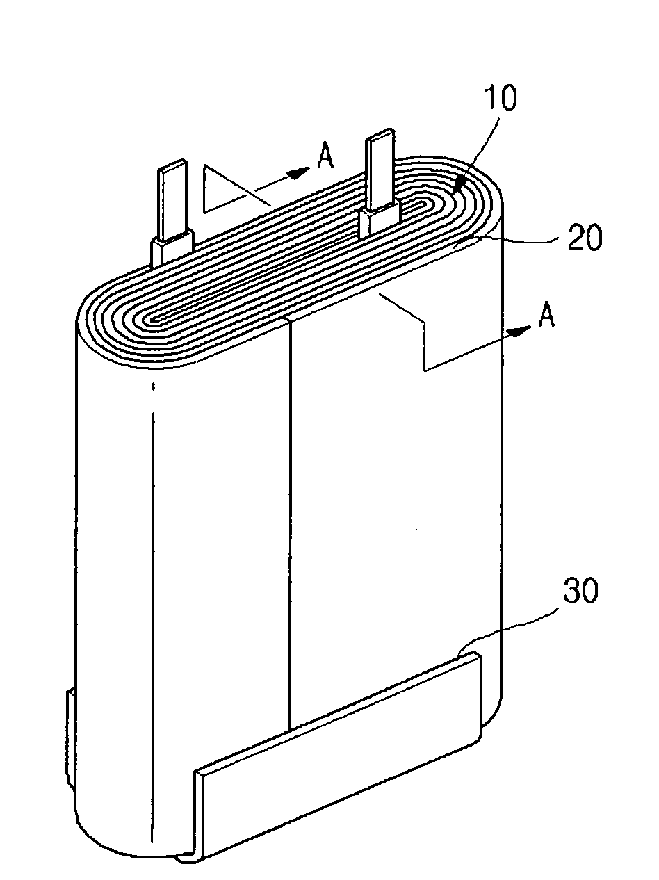
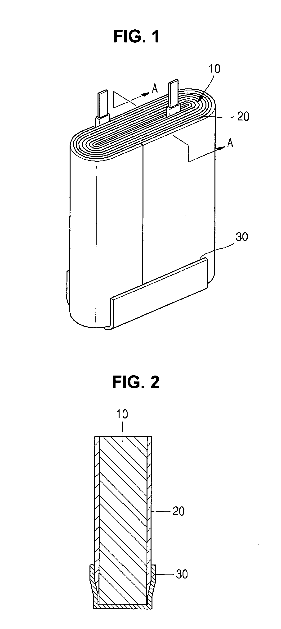
[0026]FIG. 1 is a perspective view illustrating an electrode assembly of a prismatic type lithium ion battery, and a finishing tape and a lower part tape which enclose the electrode assembly. FIG. 2 is a cross-sectional view illustrating the electrode assembly cut along line AA of FIG. 1.

[0027]FIG. 1 shows an electrode assembly 10 that includes a positive electrode plate, a negative electrode plate, a separator positioned between the two electrode plates, and electrode tabs connected to each of electrode plates. As shown in FIG. 1 and FIG. 2, the finishing tape 20 is wound around the electrode assembly 10, to fasten the electrode assembly 10. However, the finishing tape 20 covers most of width of the side surface of the electrode assembly 10 from the top to the bottom of the electrode assembly 10. A lower part tape 30 covers only the lower part including the bottom ...


PUM

PropertyMeasurementUnit
Adhesivityaaaaaaaaaa

Abstract

The provided is a prismatic lithium ion battery including an electrode assembly having a wound structure of a stack of a positive electrode, a separator, and a negative electrode. The stack has a first side edge and a second side edge, and the wound structure of the stack is formed by winding the stack around the first side edge. The wound structure of the stack has a side surface that is substantially parallel to the first side edge, and a top surface and a bottom surface, each of which is substantially perpendicular to the first side edge. A first tape is coupled to the second side edge portion of the stack of the electrode assembly, and a second tape covers a part of the bottom surface and a part of the side surface of the wound structure of the stack in a manner that the second tape does not overlap the first tape.

Description

CLAIM OF PRIORITY[0001]This application makes reference to, incorporates the same herein, and claims all benefits accruing under 35 U.S.C. §119 from an application for PRISMATIC LITHIUM ION RECHARGEABLE BATTERY earlier filed in the Korean Intellectual Property Office on the 27 Oct. 2006 and there duly assigned Serial No. 10-2006-0105087.BACKGROUND OF THE INVENTION[0002]1. Field of the Invention[0003]The present invention relates to a lithium-ion battery, and more particularly, to a prismatic lithium secondary battery having a finishing tape and a lower part tape.[0004]2. Description of the Related Art[0005]As the use of portable electronic devices increases, the use of the batteries for the power source is increasing. A secondary battery is expensive compared with a disposable battery, but it is economical as the battery can be reused by charging it. Therefore a secondary battery is popularly used for portable electronic devices as a power supply.[0006]The lithium secondary battery ...

Claims


Application Information

Patent Timeline
IPC IPC(8): H01M6/02H01M50/176H01M50/566
CPCH01M2/021H01M2/0212H01M10/0431Y10T29/49114H01M10/0525H01M10/0587Y02E60/122H01M10/0481Y02E60/10H01M50/176H01M50/566
Inventor LEE, JANGHO
Owner SAMSUNG SDI CO LTD
Why Eureka
Try Eureka