
Line driver with active termination

a technology of line driver and active termination, which is applied in the field of line driver, can solve the problems of increasing power consumption, high power consumption, and high power consumption of voltage mode line driver, and achieve the effects of reducing power consumption, accurate output impedance, and high precision

Inactive Publication Date: 2008-05-01
AVAGO TECH INT SALES PTE LTD
View PDF4 Cites 4 Cited by
  • Summary
  • Abstract
  • Description
  • Claims
  • Application Information

AI Technical Summary

Benefits of technology

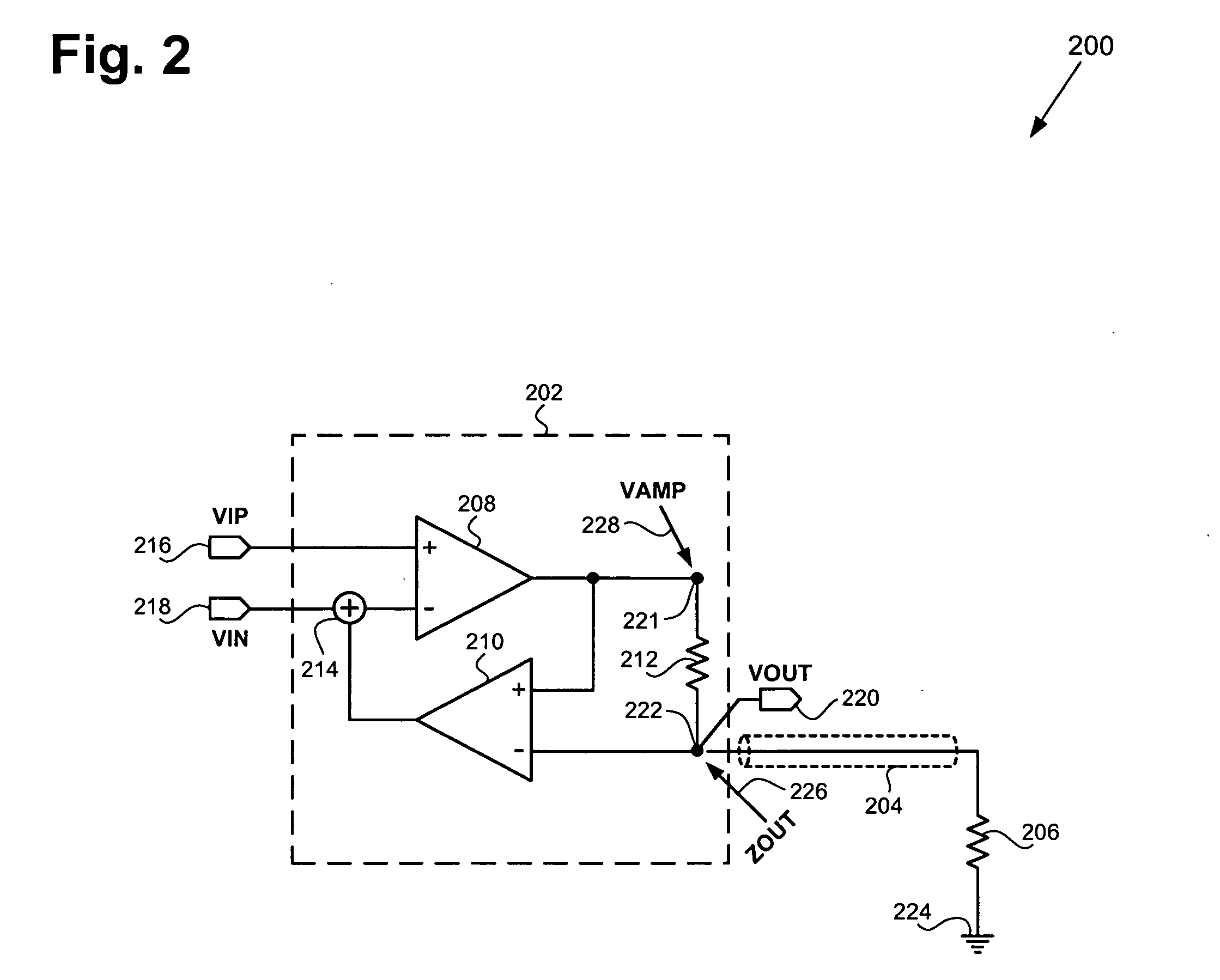
[0006]A circuit to realize high precision active termination in line drivers, resulting in accurate output impedance, reduced power consumption and improved output linearity. Features, advantages and various embodiments of the present invention are shown in and / or described in connection with at least one of the drawings, as set forth more completely in the claims.

Problems solved by technology

Although current mode line drivers can provide a desirable performance, they typically have higher power consumption than voltage mode line drivers.
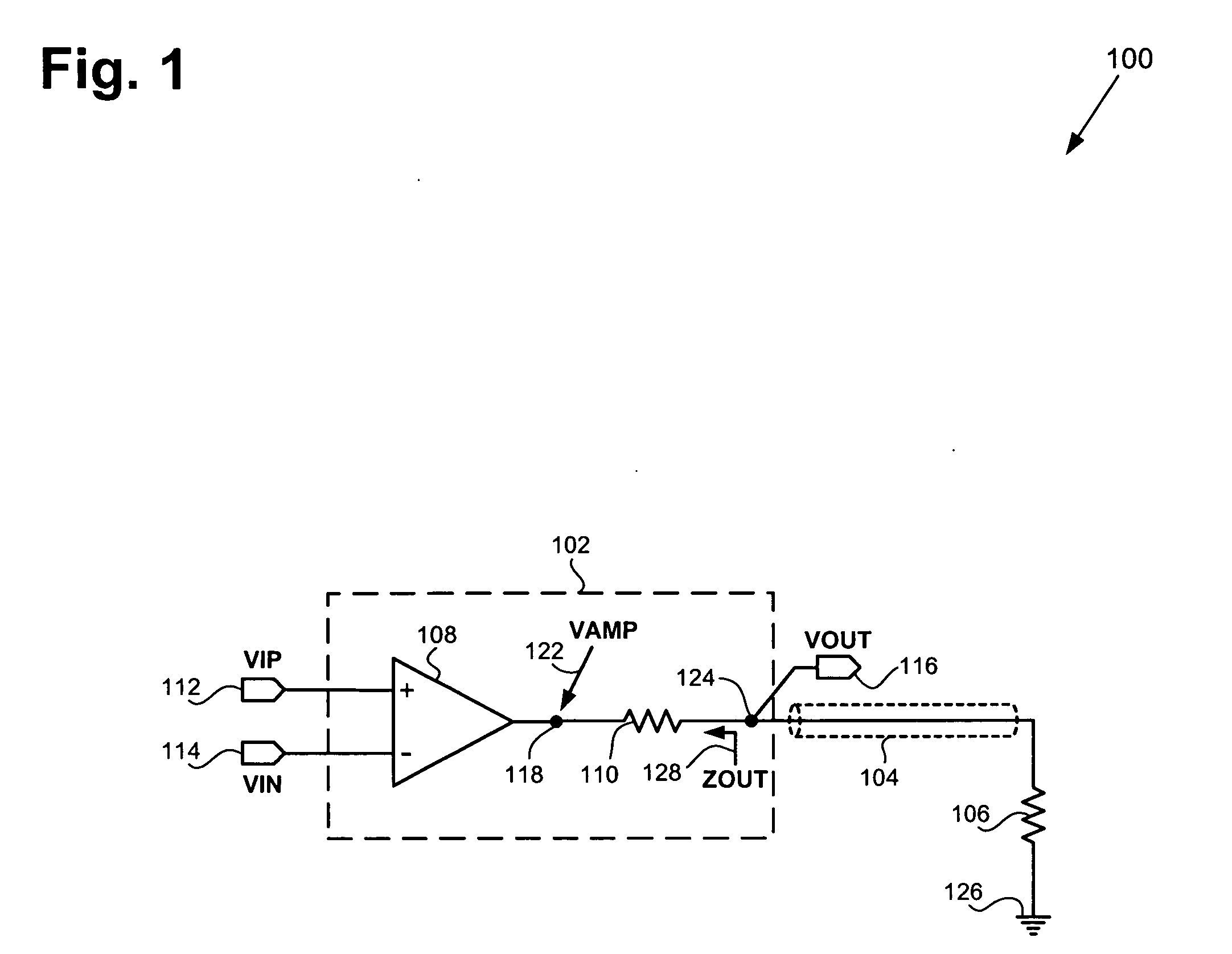
However, as a result of the voltage divider formed by the termination resistor and the load resistor, the output voltage provided by the voltage amplifier needs to be twice as large as the output voltage provided at the line driver output, which requires a high power supply voltage.
The high power supply voltage required by this conventional voltage mode line driver undesirably increases power consumption.

Method used


Image

  • Line driver with active termination
  • Line driver with active termination
  • Line driver with active termination

Examples


Embodiment Construction

[0012]The present invention is directed to a line driver with active termination. The following description contains specific information pertaining to the implementation of the present invention. One skilled in the art will recognize that the present invention may be implemented in a manner different from that specifically discussed in the present application. Moreover, some of the specific details of the invention are not discussed in order not to obscure the invention.

[0013]The drawings in the present application and their accompanying detailed descriptions are directed to merely exemplary embodiments of the invention. To maintain brevity, other embodiments of the present invention are not specifically described in the present application and are not specifically illustrated by the present drawings.

[0014]FIG. 1 shows a circuit diagram of an exemplary conventional line driver coupled to a load resistor. Circuit 100 includes conventional line driver 102, transmission line 104, and ...


PUM


Abstract

A line driver comprises a driving amplifier receiving an input of the line driver, a current sense resistor connected between the driving amplifier output and the line driver output, and a feedback amplifier sensing the voltage across the current sense resistor and providing a corresponding feedback voltage that is proportional to the output current to the driving amplifier, thereby determining an output impedance at the line driver output. Precise output impedance can be realized by using a high precision resistor as the current sense resistor, and using resistive feedback amplifiers with accurate gains as the driving and feedback amplifiers. The resistance of the current sense resistor can be substantially less than the line driver output impedance, and the driving amplifier output voltage swing can be substantially less than twice the line driver output voltage swing.

Description

BACKGROUND OF THE INVENTION[0001]1. Field of the Invention[0002]The present invention is generally in the field of electrical circuits. More particularly, the invention is in the field of line drivers.[0003]2. Background Art[0004]Line drivers, such as voltage mode and current mode line drivers, are typically utilized to drive transmission lines in cell phones, set top boxes, cable modems, DSL modems, and other types of electronic devices. To prevent return loss and signal distortion, a line driver is typically required to provide an output impedance that matches the characteristic impedance of the transmission line. For example, a line driver in a video application is required to provide a 75 Ohm output impedance to drive a 75 Ohm load via 75 Ohm video cables. Although current mode line drivers can provide a desirable performance, they typically have higher power consumption than voltage mode line drivers. As a result, voltage mode line drivers are typically utilized in devices in w...

Claims


Application Information

Patent Timeline
IPC IPC(8): H04M1/00H04M9/00
CPCH04L25/028H04M11/062H04L25/0298
Inventor WU, JIANGFENGLI, TIANWEIVENES, ARNOLDUS
Owner AVAGO TECH INT SALES PTE LTD
Learn More