Multiphase clock generation circuit

a clock generation circuit and multi-phase technology, applied in the direction of generating/distributing signals, pulse techniques, instruments, etc., to achieve the effect of high precision

Active Publication Date: 2008-05-01
RENESAS ELECTRONICS CORP
View PDF5 Cites 14 Cited by
  • Summary
  • Abstract
  • Description
  • Claims
  • Application Information

AI Technical Summary

Benefits of technology

[0019]In the multiphase clock generation circuit according to the present invention, the frequency of the multiphase clock signal to be

Problems solved by technology

When the variation in the characteristic of the lens 102 is caused, there arises a problem in that, for example, a width

Method used


Image

  • Multiphase clock generation circuit
  • Multiphase clock generation circuit
  • Multiphase clock generation circuit

Examples


Embodiment Construction

[0036]The invention will now be described herein with reference to illustrative embodiments. Those skilled in the art will recognize that many alternative embodiments can be accomplished using the teachings of the present invention and that the invention is not limited to the embodiments illustrated for explanatory purposes.

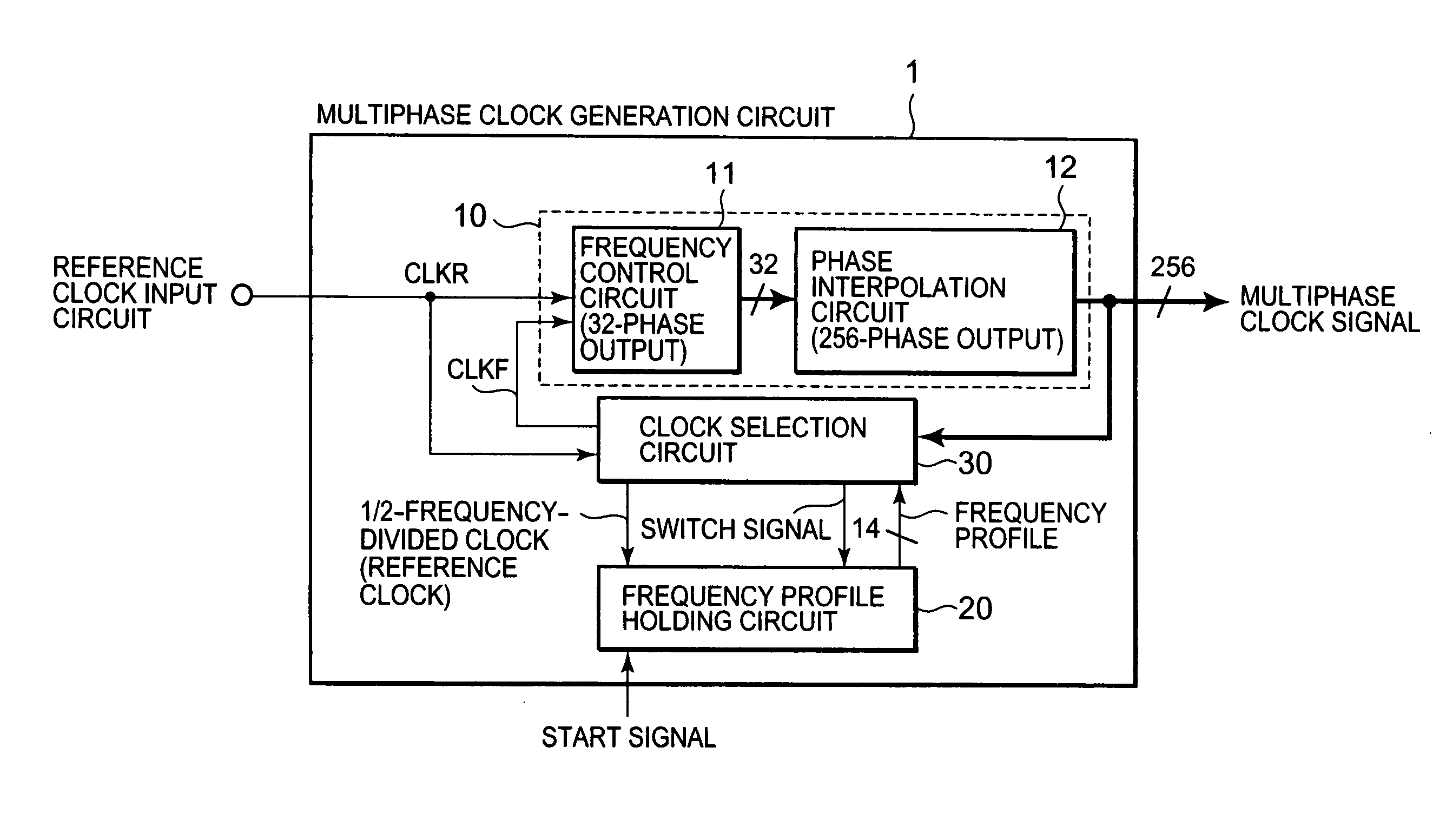
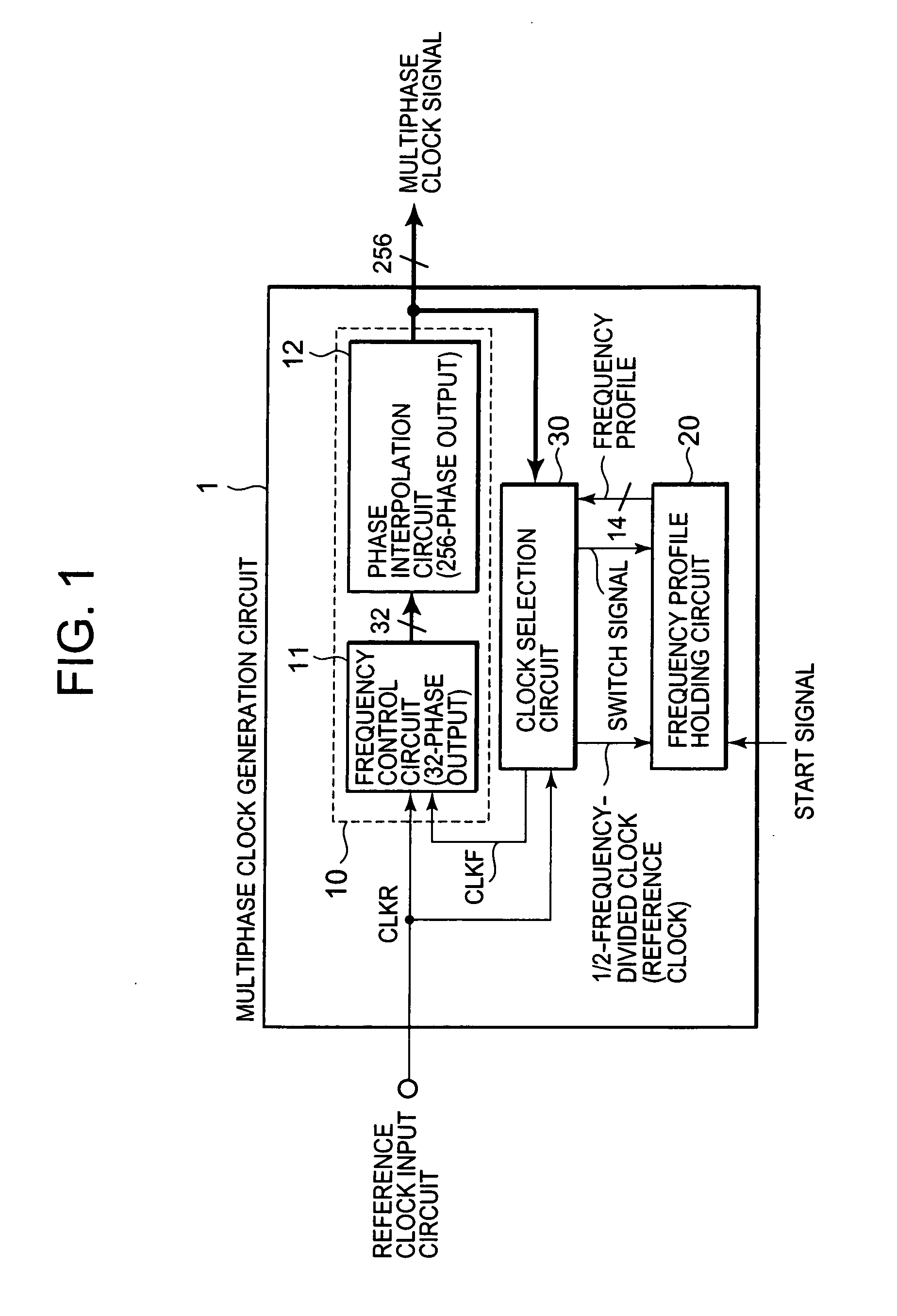
[0037]FIG. 1 shows a block diagram of a multiphase clock generation circuit 1 according to an embodiment of the present invention. As shown in FIG. 1, the multiphase clock generation circuit 1 according to the embodiment includes a phase-locked loop circuit (hereinafter, referred to as “PLL circuit”) 10, a frequency profile holding circuit 20, and a clock selection circuit 30.

[0038]The PLL circuit 10 includes a frequency control circuit 11 and a phase interpolation circuit 12. The frequency control circuit 11 controls a frequency of a clock signal to be output, based on a phase difference between a reference clock signal CLKR input from a reference clock signal i...


PUM


Abstract

Provided is a multiphase clock generation circuit (1) including: a phase-locked loop circuit (10) for generating multiphase clock signals based on a reference clock signal; a frequency profile holding circuit (20) for holding a frequency profile of each of the multiphase clock signals, starting output of the frequency profile in response to a start signal, and for updating the frequency profile with a predetermined cycle based on the reference clock signal; and a clock selection circuit (30) for selecting a clock signal with an arbitrary phase from among the multiphase clock signals based on the frequency profile, and for feeding back the selected clock signal to the phase-locked loop circuit (10).

Description

BACKGROUND OF THE INVENTION[0001]1. Field of the Invention[0002]The present invention relates to a multiphase clock generation circuit, and more particularly, to a multiphase clock generation circuit capable of changing a frequency of a multiphase clock signal to be generated.[0003]2. Description of the Related Art[0004]In recent years, a clock generation circuit is used in various semiconductor devices so as to generate clock signals. Examples of the clock generation circuit include a multiphase clock generation circuit capable of generating a plurality of clock signals with different phases (hereinafter, referred to as “multiphase clock signals”). The multiphase clock generation circuit is used as, for example, a clock generation circuit for a pulse width modulation circuit. The pulse width modulation circuit is a circuit for controlling a pulse width of a pulse width modulation (PWM) pulse which is generated in response to the multiphase clock signals.[0005]The pulse width modula...

Claims


Application Information

Patent Timeline
IPC IPC(8): H03K5/00
CPCH03K5/15013
Inventor HIRAKU, YASUYUKI
Owner RENESAS ELECTRONICS CORP
Why Eureka
Try Eureka